Electrically speaking, the field desk will have one power lead into the desk, with a double switched GPO, and a variety of DC power sources available. A task light will also feature in the design.
Electrical enclosure
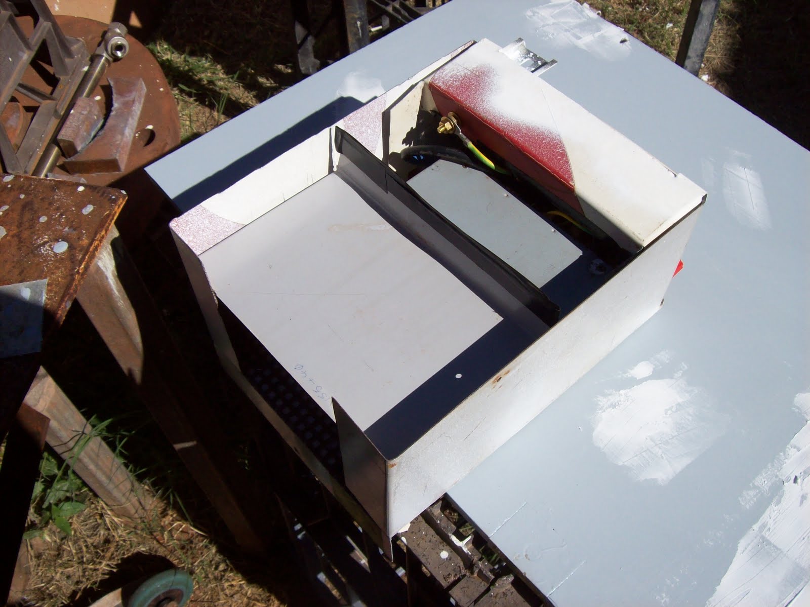
The electrical enclosure was designed to contain all components, and attach in the top of the RHS bay. The front panel will contain all interfaces - plugs, switches, etc. The original design was to use an old PSU from a 1900 series switch, but upon checking the PSU, it was found to have some of it's pins non-commissioned (-12V and - 5V) - thank fully the size of the enclosure was dictated by the GPO, and banana sockets, this meant I had room to look at alternate options.
 |
| Figure 1 - Basic Enclosure unpainted |
The front panel of the power box is made of 3-4mm thick plexiglass, drilled, cut filed to hold the GPO, IEC socket, and banana posts. To prevent scratches showing on this panel, I marked the terminal values on from the back, and then spray painted over them from the back - this means the paint cannot be scratched from outside the case. Interesting note was when the paint dried, I could suddenly see this invisible cracks around the banana posts - it looks almost surreal to see "reversed cracks" filled with paint.
The enclosure is designed to sit in the top of the field desk, therefore all ventilation is through the floor (or the front) - I simply replaced the floor with some punched mesh, and then used sheet metal shields to redirect any airflows from the back, through the PSU fan, through the PSU, and then into the front section, through the enclosure floor. Each "side" of the PSU has around 12 sq inches of floor vent available to induct, or expel air.
The enclosure (power box) is held in the top of the desk by means of some brackets, and a folded lip at the back. None of the retaining hardware obscures the ventilation grid, and removal of the power box is accomplished with the removal of one screw, since the forward brackets tilt to permit removal.
 |
| Figure 2 - Close up of front panel, with first sheet metal divider removed |
 |
| Figure 3 - Mesh base to enclosure used for ventilation of PSU |
A 12V LED lamp was purchased from the local variety store (KMart) - I had looked at an incandescent lamp, but compared to the LED lamp, it was pale and yellow. I considered one of the halogen lamps I use when I sew, but they do throw some heat, and I considered that would not be wise in the planned location - not to mention wasted energy as heat.
The lamp was gently disassembled (no warranty voiding yet) and tested for it's ability to "hold up" from a horizontal plane - it was discovered that if held at a 45 degree angle, the lamp's "flexible arm" would support the lamp to the maximum reach. Based on that, a bracket was made (from plexiglass) to hold the base at 45 degrees. The bracket slides into a short length of DIN rail which is used as a track. This track is part of the enclosure and is accessible from the front panel.
 |
| Figure 4 - Power box in place in field desk with lamp inserted |
PSU
Since the planned 1900 PSU was abandoned, the next most affordable option was to use a surplus ATX PSU. There are a number of articles on the web which discuss the conversion - most centre on forcing, or redirecting the softpower "On/Off" wire, and providing a load to stabilise the regulation circuitry. I started going through my collection of surplus ATX PSUs looking for a reasonably low powered unit which worked, and could be used in this project. I tested some of my surplus ATX PSUs and found a 450W which worked OK. I originally planned on using a "wiring harness" to connect everything up, but the space was too tight for that option.
 |
| Figure 5 - Wiring harness (Mk 1) which was too big for use |
 |
| Figure 6 - Internals of ATX PSU being modified for use. |
 |
| Figure 7 - Modified PSU in enclosure with earthed divider panel. |
 |
| Figure 8 - Completed power box with second divider in place for ventilation redirection. |
 |
| Figure 9 - Completed power box ready for use. |

No comments:
Post a Comment