Article Index Pages

Monday, April 26, 2010

Homemade Anvil - RR Anvil - Part 2

Part 1 talked about a home made RR-anvil which I designed, and had built with a lot of assistance from some of the guys in one of the workshops at work.

As mentioned in part 1, the issue is to stop the ringing by thickening up the web, and helping transfer any forces from the table to the base.

In an article in one of the 1920-ish shop notes from Popular Mechanics the article talked about making anvils from I-beam and thickening the web by bolting a piece of wood on each side of the web... based on that idea I made a number of pieces of 1 1/2" reinforcing steel which fitted between the rail head and the base plate of the rail.


I then cut another set of pieces which would sit between the underside of the table, and the base.


The next step was to cover the reo-bar. I used some scrap 4mm galv sheet I had kicking around. It welds easy enough, and is thick enough to stand some abuse.


The pritchel hole at the back of the anvil needed to be protected from whatever I did, so I cut up a piece of pipe to make a hollow in the back of the anvil so the underside of the hole would always be accessible.

The sheet metal shroud covered all the reinforcing bar sections welded in underneath the head, and table. Since the rail is made of high carbon Japanese steel, and my welding capabilities didn't seem to like that too much, I ensured mechanical locking whenever possible to make everything sit properly. Knowing that this would not suffice in the long run, knowing the welds made to the rail would crack under repeated hammer strikes, the next step was to fill the gaps so the reo-bar would not move under any circumstance.

The shroud was completed, with just a simple plate (about the size of a credit card) left unwelded at the back.

I obtained from the local tyre place a few bucketfuls of lead tyre weights, and melted them down using a wok burner, and one of my furnace crucibles. I could have used the furnace, but was concerned that over heating the lead might create fumes. I used the furnace when I was melting aluminium, brass and bronze since there wasn't significant issues with fumes... I was not as familiar with lead (I'm not a fishing guy who makes sinkers), so did not know how the fumes went with excessive heating. The wok burner was slower, but I figured there'd be less in the way of fumes.

Using the foundry robot, I picked up a 7L crucible of molten lead, and poured it into the gap between the shroud, and the internals of the RR-Anvil, effectively filling the gap. All surplus molten lead was poured into one of the ingot trays I use when pigging aluminium.


The lead was allowed to cool, and the final plate was recessed into the lead, and welded in place, effectively sealing in the lead. A test with the hammer and it was sweet - no ringing at all.

Here is a photo of the painted up anvil showing the recess under the pritchel hole...

And a side view of the painted anvil...

Yes, the final weight now exceeds it's original weight by more than 100%. The anvil started at 26Kg (57 lbs), and now weighs over 55 Kg (121 lbs).
The slots cut in the base web are for securing the anvil down on a wooden base, and the wonderful "imperial plum" purple paint is one of my garage sale paints I use to paint up things that need protection. I've left the top faces unpainted since it's unlikely the paint would survive the use of the horn, cutting table, and main table.

Now the anvil is finished, I've already found it too small. I've used it for a number of small jobs and for those purposes, it's fine. But once I start pointing bladeware, or other items longer than 8" at it, the table is too small. I've considered welding a larger table on top, using the existing table as a weldment anchor. I have some 2" plate here which could be used, but I'd be back at the workshops to have it cut and welded on the big machines.... I only have one small piece and I can't afford to replace it if it's spotted by a boss.

For now I limit my work in size, and am on the hunt for a decent size anvil. I'm playing with a "false table" idea to allow larger work, but that's had to take the back seat for other projects lately. The "false table" is effectively an extension of the "third hand" concept used by some smiths... a set of light gauge supports are used to retain, or hold the work on the anvil, but they aren't actually part of the anvil. All striking would still occur on the anvil, but the false table would permit me to ensure the work was level, and flat when it is on the table... still in Mk2 testing....

Homemade Anvil - RR Anvil - Part 1

Anvils are one of those things which can be "home made", or totally unorthodox, but it's hard to make a cheap home made anvil which is good, and matches the traditional pattern.
The biggest issue with home made anvils is mass, and "ringing". People tend to make them too light, or out of materials which ring. The first anvils I made were made of material which was too soft, and would scar when I attempted to flatten coat hanger wire on them, let alone anything substantial.

I was given access to a source of rail offcuts, and so was able to grab a number of lengths of rail ranging from 200-1200mm (8" - 48") in length. Since oxy cutting is not in my list of proficient skills yet, I asked one of my friends in the workshops to cut the rail for me. I also provided a sizable piece of 1-1 1/2" plate and marked up a "table" to be cut at the same time. Payment for getting the cutting done was to supply additional lengths of rail offcuts so other anvils could be made.
Sounds good, and it was... the problem was some of the "bosses" spotted my anvil in the workshop whilst it was being cut - each time the bosses would spot it, they'd claim it. The workshop would then start another one for me, and another boss would walk through. By the time I got my anvil, all the heavy plate was used up, and I had refilled the rail offcuts bin at least twice. I don't relate this story to criticise the workshop - far from it. I relate it to show that most people who work with metal like the idea of having an anvil, but would rather someone else made it. If I could afford the purchase and shipping on a commercial anvil I'd have bought one..instead I made one.

To reduce the demand on the workshop, I only asked them to do what I couldn't easily do at home, or to do what was considerably easier (and more efficient) to do with the machines at work.
I asked them to rough cut the rail with the oxy, and to cut the table from the 1 1/2" plate with either oxy or plasma cutting.
I asked them to drill a pritchel hole in the table of a minimum of 1/2" diameter.
I asked them to weld the table to the head of the rail, with appropriate overhangs, clearances, etc as per the drawings and templates I'd supplied.

From what I understand, the guys who'd made my anvil were apprentices tasked by the tradesmen between jobs. I am led to believe that the two apprentices ended up making at least 8 anvils prior to mine, and had at least another 4 to complete after mine. After all that, I'd have expected them to be cutting corners, and generally sick of making something, only to have a boss claim it. When I collected my anvil, I was most pleasantly surprised with how much work they'd done over and above what I'd asked... all the finish grinding was done, there was practically nothing left for me to do other than a few minor alterations.

Below are pictures of the anvil I ended up with. I'll point out the features and the reasoning behind them.

The feet are deliberately cut so they are under the tip of the horn. I read on one of the blacksmithing sites that when someone builds a RR-Anvil (Rail Road Anvil), that by making the base extend under the horn, the force from strikes is transmitted to the base better, and is less likely to cause issues through the web.

The table ended up slightly smaller than planned due to the loss of materials. The table is roughly 150x200x19mm (6" x 8" x 3/4"). A section of bare rail head had been left uncovered for the cutting table.

The table is welded to the rail head on all four sides. I don't know what the trick is the workshop guys used, but their welds to the high carbon rail have excellent penetration. When part 2 comes along I will be able to tell you that nothing I tried worked anything as well as what the workshop guys did.

The RR-Anvil (Mk 1) weighs in at 26 Kg (57 lb). Is it heavy enough?
Does it work?

I tried the anvil and found it rings like the proverbial bell. I don't know if the original anvils I tried to get made turned out, but with some perverse pleasure, I really hope the ones claimed by the bosses also ring as badly. It's mostly the thin web through the middle of the rail section which causes the ringing, so odds are all the other anvils made will also ring.

The way to reduce the ringing is to increase the mass of the web. Some people accomplish this by wrapping the web in chain.

I tried it, but no luck. It still rang badly - subdued slightly, but still quite uncomfortable.

Part 2 will cover how I got rid of the ringing, and ended up with a very serviceable, albeit small anvil.

Sunday, April 25, 2010

Bolt cutter repairs

Bolt cutters, aka "The keys to the city"

Long story short, I bought these ages ago - a generic set of 900mm (36") bolt cutters with a nominal capacity of 3/8". I bought them for cutting up expanded aluminium to drop in the furnace for melting.
I loaned them out so someone could cut up some 1/4" and 3/8" reinforcing rod, and there was a hard spot in one of the 3/8" rods - the paper thin handles didn't stand up to the use and tore.

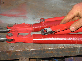
So as a result, I had to repair this tool. I cut the remaining handle piece from the head castings by careful use of a sharp cold chisel. I tested the other handle by trying to cut some 3/8" rod
and a temporary handle, it failed as well - most likely find the other handle was weakened, but not visually damaged.


I tested some of the pipe sizes in my rack and found a couple which gave good slip fits, with wall thicknesses around the 2-3mm mark.
I made some replacement handles about 8" (200mm) longer than the originals, drilled some 11mm holes and welded some 10mm nuts on so some 10mm bolts can be used to retain the pipe handles onto the head castings.

I painted the pipe handles up since they wouldn't be used too often.

Once the replacement handles were made, I built up a "tool" to hide in the end of one handle. Made from 25x6mm (1" x 1/4") flat bar, the tool serves two purposes...

a - open ended spanner to tighten/ loosen the 10mm bolts

b - a 3/8" slot to serve as a "go-no go" gauge for testing material to be cut.


Removing the tool from it's storage in the handle end.


Testing the spanner on the retaining bolts

a piece of 3/8" rod passing the "go" gauge.... compared to

a piece of 1/2" reinforcing rod failing the "no-go" gauge.

I've since loaned the colt cutters back to the guy so he could finish his job, and it worked well.

welding cart

The welding cart was built to overcome the issue of always working on the ground. For some tasks, the cart is not suitable, and the welder is removed from the cart, and taken to the job, or the cart is simply left near the job, but the earth lead is disconnected from the cart, and clamped to the job.
The welding cart offers another advantage - one of a "large earth"... All my welding experience up until I built the cart was based on attaching the "earth clamp" to the piece being welded. Sounds good, but sometimes it's easier said than done. I had seen other people clamp to a large sheet of steel, then drop delicate work on the sheet, and use it's contact with the sheet as the return path. The entire cart is like that sheet of steel. The return clamp is attached to the cart (in my case by the clamp being attached to a tab on the underside of the table) so anything I place on the top of the table can become part of the current path, simply by it's electrical contact. This simplifies any delicate work considerably, and allows repositioning without fighting with the return lead.

I'll talk more about the welder itself in another page, but it has been considerably modified to make it more usable for the kind of things I want to do with it.

The cart was made from salvaged materials. Most of the sheet metal was cut from a discarded instrumentation cabinet. the steel is all 1.5mm (about 1/16") thick, and was powder coated/enamelled. The cabinet was basically cut so the top and bottom portions became the top and bottom of the cart, but the sides were replaced with other material.
The main structural components (frame, uprights, etc) were made from a rolled shape which I got from the tip. The cross-section resembles a squared up letter C, and it came in lengths of 1200mm (4') with grey paint on it. I believe it was some kind of packing material for shipping motorcycles, but I really can't be sure. The steel is 2mm thick, and the C shape is basically 30-35mm wide, and 19mm (3/4") deep. The slot on the open side of the C is 10mm (3/8"), and a 3/4" square tube will ride inside the C section if one corner is protruding through the slot (I used this exact concept to make the leaf folding mechanism)


Construction was basically determining the finished height, and then making up the side frames to that height with the top member equal to the width of the cabinet top.
The frames were welded to the top and bottom pieces, and some cross pieces were cut and welded in to form a "shelf" in the middle.

The middle shelf does not extend across the entire width of the table, since I determined it would be prudent to have the full depth of the table available on one side for hanging cables. Additional cross beams were cut and welded in to form the sidewall of the middle shelf, and some hooks were welded in on these beams for hanging cables.


The original build on this cart had four wheels, one at each corner, but within a very short time, I determined was troublesome - firstly for the issue of uneven ground, but mostly since the cart would move under the forces of grinding, or other metal abuse activities. The front wheels were cut off, and some 3/8" nuts were welded into the front pillars. Some 4" long cup-head bolts were screwed into these nuts, the heads of the bolts forming the feet for the front of the cart. A telescoping handle was added into the shelf beams, to assist in lifting and moving the front of the loaded cart. The telescoping handle is nothing more than a piece of the C section steel tubing, with another piece of 3/4" square tubing inside it, some stops welded in, and a "handle" to make it easy to pull out.

The telescoping handle can be seen just above the top PVC tube, extended out approximately 6"

The top of the bare cabinet was about 400mmW x 500mmD, and adding the widths of the two support frames either side only added another 70mm to the overall width - not nearly enough room for any serious fabrication. A means of making the table top larger was required.
One of the cut away sides was stiffened up by welding a piece of "C" tubing at each end, the original folded edges were sufficient for the sides since the folds were 3/8" deep, and 3/8" wide, 3 sides of a perfect square.
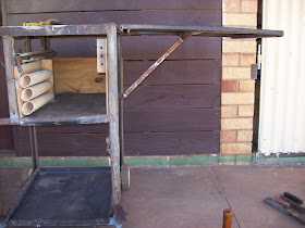
Some hinges were padded out, and screwed in place for the drop leaf, and the salvaged rear axle of a dumped lawn mower was used for the hinge of the brace. The ends of the axle were trapped in some short pieces of 3/4" square tubing which was tacked under the sheet metal leaf.

Photo taken from underneath the raised leaf, showing the brace, vertical track, and it's joints.

The other end of the brace is bolted to a "shuttle" which runs in a vertical track. The shuttle is nothing more than a piece of square tubing running in another piece of C tubing, with a tab welded to it for the brace to bolt onto.
When the leaf is dropped, the shuttle is in the bottom of the c section track, but when the leaf is lifted into position, the shuttle moves upward, and trips a weighted pawl which prevents the shuttle returning past it. This pawl keeps the lifted leaf in the "up" position, level with the permanent table top. The pawl is released via a lever at ground level which can be activated by the operator's foot.

The locking pawl as viewed from under the shelf. The release mechanism, and counterweight is operated through the 3/8" rod which acts as an axle for the pawl. All joints are simple clearance holes through scrap steel, nothing fancy.
Top photo - leaf lowered

Photo of leaf raised


The welding cart has evolved a little over time, the middle shelf had some lengths of PVC pipe added for providing storage for welding rods (2.5mm and 3.2mm), and a block of wood with some holes drilled through it was added for holding the "live" electrode (handpiece) in an insulated holder so I could put the handpiece down during a job, and not worry about current flowing (the lesson on that effect was most uncomfortable).

The 3/8" cup head bolts failed recently (see Hose suspenders page) when I wheeled the cart out in the street so I had enough room to turn a 4m (12') length of 3/8" square rod through a jig clamped atop the welding cart. It was during the repairs that these photos were taken. The 3/8" bolts, and nuts were removed, and replaced with some 20mm (~3/4") anchors and nuts. I don't know what the anchors were for (part of a toolbox full of junk which I found on the side of the road - it's amazing what falls off trucks around here), but it's nice to use some of them up.


That's about it - I know I took better photos during the construction of the cart, but I don't seem to be able to find them. I know the cart looks rough, and I'm really not in the mindset to go nuts painting things like this when all they do is get dragged between the shed, and the job. I paint things which will spend more time "sitting" than working, unless painting is needed to protect the "thing" - given this cart is my biggest workhorse, I don't see the point painting it. If fact, I have to periodically run the grinder over the top every month or two to remove any rust, or paint which would stop the current flowing through the top and whatever workpiece is on it.

A lot of what was built when I first set up here was built from scrap I collected from friends at work, and the local tip (Salvage). I'd just moved to start this job, and disposed of all my building materials for the move. You will find a lot of what I describe and show in these pages will be made from salvage/ surplus materials. Some if it is my desire to save money, most of it my desire to reuse materials, and find uses for "junk". I read shop notes books from the 1900's for fun, and do not subscribe to the throw away mindset that many others have.

Friday, April 23, 2010

Hose suspenders - Part 3

The other major component of a hose suspender is a loop of rope which is wrapped around the hose (lark's head method if you're interested) prior to hooking the hose suspender on one of the ladder rounds.
I obtained several metres of 15mm polypropylene rope for this project and did consider splicing the rope, but came up with another method which reduced the bulk, and rigidity of the rope.
I was concerned that if I spliced the rope into a loop, I'd effectively double the cross-section of the rope at the splice, and thereby reduce it's flexibility.
I decided a better way would be to use the method of splicing used for making "quoits". This method does not change the cross section of the rope, and therefore doesn't change the flexibility.
To make a quoit, you determine the diameter of the loop, and then roll out three and one half turns of that diameter - see photo below.
You then separate the three strands of the rope, and using only one strand, reform the loop. You will find a point in the loop where the strand "sits" nicely into the twist of itself. I looped the strand through the eye of the hook as part of the first loop, and commenced the twist as shown below...

You basically reform the twist of the original rope by threading it around itself as you move around the loop. The strand will settle back into it's original twist, and forms up nicely as if never unwound. The picture below shows the second turn coming around, and commencing the third turn.


As seen above, where the three turns have been made, the rope looks normal, full diameter, and no unusual lumps or bumps.
Once three full turns are made, you have to join the strand to itself. For a quoit, you'd normally do something a bit fancy, but for these hose suspenders I simply took a heated knife blade, and cut the two strands so they overlapped by 3mm (1/8"). I then heated the knife blade again, and placed it between the two ends so they both heated, and then withdrew the blade so they came together and fused cold as one strand.

I have a collection of "garage sale" utensils which are used for this sort of abuse - there's no way I'd survive sticking one of our kitchen utensils in the flame of a butane torch - quite simply, "the Boss" will string me up.

The hose suspender weren't the only things done... I also made up three suction line ropes (15M) long, 56 lanyards for salvage sheets (1.8M long), and the 9 hose suspenders.

Lessons learned? don't cold forge 3/8" rod without strong tooling, and if necessary, use cuts to weaken the rod for tight bends... also, don't put "the paint is dry" hose suspenders on the kitchen table to splice the loops unless the paint has had at least 2 months to dry... 48 hours is not enough with thick paint, and for some reason what doesn't come off on your hands, will come off on the table cloth - sorry dear.

Hose suspenders - Part 2

I tried using a similar method of bending the tighter curves for the "square hook", but it was too tight a turn, and the forces tore the slipper apart. I was back to either forging, or some other method. (Trust me, I want to forge, but I also want to reduce the number of outstanding projects first.. once I reduce my workload, then I'll fill it back up again)
In the absence of forging, I decided to cut the rod and using the cuts as weaknesses, bend and then reweld (sort of like scoring cardboard to bend it)


The above photo shows a piece of rod with the cuts made, and another piece already being bent using the cuts as a weakness.


This photo shows how the pieces come together to make the finished hook. They are welded together as part of the construction, and the cut rod will have the exposed areas built up by welding.

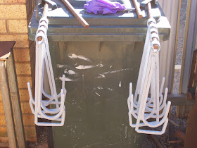
Nine hooks welded up, all cut areas built up, both hooks joined at the top, bottom, and back, and the ring added.

A note about the rings. They started life as an offcut of scrap I fished from the scrap bin. I cut them into 1" (25mm) long pieces on the cutoff machine (aka drop saw) and then took them home. I chucked them in my lathe, and deburred them inside and out. I then turned a deep 30 degree chamfer on the inside at each end of the pipe section.

Once everything was welded, I hit then all over with a flapwheel in the grinder (these things are amazing!!! never used one until Bender - Now I'm buying them online whenever possible)


The results of flapwheeling the hooks was pretty good, I found a few welds to redo, then got the hooks ready for painting - the primed hooks shown below.


After two coats of primer, I painted two coats of epoxy paint over the hooks. It's "handrail yellow" supplied from the fitters at work. I reason the paint stands up to a lot of knocks and scrapes pretty well, and the bright colour will help the equipment stand out, and not be missed on the fireground. From memory the paint brand is "Galmet" - I can't be sure since I returned the tin once I was finished with it. The primer was the same primer I used for Bender - local "White Knight" steel primer.


Part 3 will cover the other part of the hose suspender.

Hose suspenders - Part 1

OK, I'll openly admit it, I'm not a tradesman... I'm a dabbler. If you haven't already noticed it, some of what I show in these pages are mistakes, errors, and substandard welding. It's not from a lack of wanting, just a lack of training. Half of what I put these pages up is to show what can be done, the other half is to show what shouldn't...
I was once told that a Wise man learns from the mistakes of others - learn from mine. (you won't have time to do them all yourself!!!)

I offered to make some "hose suspenders". These are used by firemen for securing hoses running up ladders during structural fires. The suspender comprises two main parts, the first being made of steel, and resembling a large fish-hook. A sketch of it is shown on the welding table below....
The one I saw (to take dimensions from) had been forged from 3/8' (10mm) rod, but since I haven't built my forge yet, I figured I'd built these from welded pieces of steel. The ring at the bottom would be made from small pieces of pipe, and the two "hooks" would be made from 3/8" rod.

I obtained some 3/8" rod from the workshop, but all that was available was square rod, not round. I decided to make the "round hook" first by bending the rod around one of the pipe offcuts left over from Bender's legs. I welded the offcut to a scrap of steel as a jig.

The above photo shows the steel in the jig (Mk1) - all chalked up for the photo, and the arrow pointing the direction of the bend.

Cold bending 3/8" square rod was fairly easy, but getting it to conform to that curve was not easy. Sure I could have threatened it with the hammer, or swore at it, but I needed a better plan.

Mk2 jig basically added a "slipper" to the bend - a 1/2" (13mm) rod was welded in the centre of the pipe via a hole and plug weld, and a pipe handle was made to hold a slipper against the rod being bent. The slipper was nothing special, just a 1" (25mm) piece of pipe dropped over a 1/2" (13mm) rod.

The slipper keeps the 3/8" rod against the former in the jig through the entire rotation of the slipper pipe. This forces the rod to bend just as tightly all the way around the 180 degree turn.
The photo below shows the Mk2 jig, with the pipe (and slipper) at the commencement of a bend

about 20 degrees through the bend, I would place the larger yellow pipe on the slipper pipe as a handle to increase leverage, and then complete the bend

I found it easier to place my body between the end of the rod, and the pipe handle, using my hip to guide the rod stock, and my hands to guide the pipe. Sounds awkward, but it was actually easy, and quite quick. Once the rod was bent, I aligned it with a mark on the jig, and cut it off with the grinder, and started again. All up, nine hooks were made in about two hours including making, and remaking the jigs.
Part 2 will cover why the same solution failed for the other hooks.

Foundry "Robot" - part 3

The controls for the robot are all located at the operator end of the device. The controls primarily comprise a pair of handles at 90 degrees to each other for swinging, turning, and moving the main beam (3m (10') pipe) through the spigot, tilt, and sleeve joints. The two handles are attached to the beam via a sleeve which is pinned to the beam with a thumbscrew. This allows the handles to be moved if the operator prefers a clockwise pour, or anticlockwise pour.
The end of the pipe beam is left exposed, and open to permit the future (possible) addition of counterweights should they prove necessary, although as yet they haven't, even when the robot was used with 5L of lead used to deaden a homemade anvil.

The control for the gripper is a simple push-rod which activates through a handle located at the operator end. At the gripper end, the push rod operates a slug which is linked to the gripper bell-cranks, whereas at the operator end, the push rod is connected to a handle which can be locked at any point of it's operating range.

In the above photo, the gripper control handle is back, towards the operator, and the grippers would be open. The arc shaped plate (quadrant) is actually the remains of a 9Kg (20lb) Propane cylinder top, left over from making a "George Vortone Muller".
The quadrant has a series of cuts in the edge made with the cutoff wheel of an angle-grinder. The lever at the top of the operating handle lifts a locking bar which engages with those cuts - similar to the rachet and pawl mechanism in a handbrake.
In operation, the user grips the crucible by squeezing the lever, and then pushing the handle forward to close the gripper. Once the crucible is gripped, the lever is released and the handle stays in that position. A small amount of "spring" is in the system to permit minor positioning errors in the cuts on the quadrant.

The above photo shows the griper control in the closed position.


The next sequence of photos shows the approach of the gripper to the crucible
Then the nose piece locating on the tang
and then the gripper closing on the crucible
At this point, the crucible can be picked up, and moved through all the axes of movement the robot offers, including pouring...


That pretty much covers the robot.. I did find one misplaced photo of the gripper mechanism without the fingers bolted on - see below. It helps clarify what I was trying to say about the mechanism being separate from the fingers and nosepiece.


The main thing this robot forces me to do is lay out my foundry area properly. I am constrained
by the centre of rotation of the robot, and the reach of the beam, and sufficient area to work in. I found these constraints allowed me to divide my work area into three distinct "zones" - HOT, WARM and COLD.
Hot is where the furnace is - pretty self evident.
Warm is for molding, pouring, degassing, skimming, etc.
and Cold is for charging, or loading the crucible.


If I pickup the crucible from the cold area, and use the robot to load it into the furnace, then I am guaranteed that it will have it's pouring lip pointed where I want it for the pour.

The robot is tall enough to permit me to place metal on top of the furnace for preheat, but I only do that when necessary - which isn't often here.

So, to sum up... The robot offers the advantage of not needing any significant lifting, in fact the heavier the crucible, then easier it is since your own body weight can be used to counterbalance the load at the gripper.
The gripper can be modified by simple bolt on fingers, and nosepiece for different crucibles, or to replace corroded parts.
The robot encourages the layout of the foundry work area into zones based on tasks, and risks
The robot can be built from scrap, and is fairly intuitive to use.
The robot permits a single operator to load, pour, reload, etc crucibles up to A30 without the use of a second person, with enough accuracy in the pour to pour water into the neck of a 2L coke bottle, and only lose 100mL (5% loss pouring into a target of 3/4" diameter at 10' away.)