The Motor Mount
The original lathe stand used a jackshaft mounted on a wooden slide-way for a clutch, and speed control was limited to the cone pulleys on the motor/jackshaft - and then the standard Taig 6 speed cone pulley.
The new motor system would have the motor speed controlled by a VSD (Variable speed drive) giving infinite speed control over the range of 0-100%.
I still wanted a clutch (unloader) so I looked at various designs used by others and cobbled up a version of my own.
The belt tension aspect of the motor mount is loosely based on a design shown on Nick Carter's website. (www.cartertools.com)
His design uses rods for alignment, and a threaded rod for adjusting the position of the moving member. My design uses slots cut in the mount for alignment, and a threaded rod for adjustment.
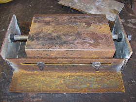
The basic structure is made of two pieces of 50x50x3mm angle iron (2" x2" x1/8") welded together to make a channel 100mm wide and 50mm deep (4"W x 2"D). the length of the pieces is approx 200mm (8")
I then cut 2 pieces of 50x50x3mm angle iron at around 300mm (12") long and cut slots about 12mm (1/2") from one edge. The slots were a clearance fit on standard 6mm bolts. (Slots were cut using drills to mark the ends, then 1mm cutting disc in between)
Corresponding holes were drilled in the piece made earlier in the description, and 20mm (3/4") bolts were tacked into place so the threads extended out through the slots.
End pieces were measured and made up to close out the end of the longer pieces, as much for stability, but also to support the threaded rod used for the adjustment.
The moving part is driven by a nut which was threaded in, and then tack welded to the underside of the moving part.Nuts spun on to the threaded rod, and welded in place became the thrust surfaces for the rod's action, and one nut was welded in place out the front of the unit for adjustment purposes.

Figure 1 - base of motor mount - sliding parts.
The pieces already described do not actually mount the motor, instead they provide a base which can be adjusted. The part which actually supports the motor is a hinged channel (cut from the side of some 100x100x3mm square tubing) so it actually 100mmwide, and 15mm deep.
A corresponding piece is fabricated from 4mm plate to sit atop the moving motor mount part made earlier, and to support the channel piece just described. The channel piece supports the motor by means of 2 slots cut in the channel at right angles to it's long axis - these permit adjustment of the motor position along it's shaft axis.
The channel is hinged onto the mount plate, and a cam is placed near the mount hinge to change the angle of the channel. The cam was built by cutting an approximate shape from 4mm sheet, then tack-welding a 15mm wide strip of sheet around the cam surface for wear reduction. The cam has a position where the "lifting effect" is stopped - this is the position where the motor is tilted back away from the headstock of the lathe.

Figure 2 - the built up cam which tilts the motor mount channel.
So the overall structure is:
the motor tilts forward and backward within a range of motion governed by a cam (35mm = 1 1/2")
which sits atop a sliding mechanism which adjusts belt tension over a range of 75mm (3")
The motor can also move along it's shaft axis by 25mm (1") via the slots its mounted in.
The cam is operated by a wire lever about 250mm (10") long located well out of the way on the LHS of the cabinet.

Figure 3 - completed motor mount assembly
A standard steel ruler pinched under one of the slide nuts was used to test the range of the tilt mechanism

Figure 4 - Motor mount system in the unloaded (belt tension released) position.
The recorded range of motion was approximately 35mm (1 1/2") between unloaded (no tension) to the loaded (tensioned) position.

Figure 5 - Motor Mount in the loaded (tensioned) position.
Why have the facility to drop belt tension via the lever?
#1 - ability to leave the lathe when not in use with the belt un-tensioned to prolong belt life
#2 - easier changing of positions of the belt on the 6 speed pulleys
#3 - less chance of driving the motor when moving the spindle by hand (new motor is a PM DC motor which would act like a generator if I spin the chuck by hand)
So based on this design whenever I change the belt, I would place the belt on the appropriate pulley range and push the lever up into the "loaded" position.
I would then use a 17mm socket to adjust the threaded rod and move the sliding part so the belt tension was where I wanted it.
Then I would use the lever to reduce the loading, and adjust speed ranges accordingly.
In testing, I have found the flat section on the cam is sufficient - I can "feel" it click in through the handle, and the tension stays constant during use.
Next couple of posts:
I have photos of the frame construction, basic sheet metal work, and the construction of the control panel i can access. It doesn't cover much of the control electrical system, but does cover the fabrication of the switches, and the panel-work itself.
No comments:
Post a Comment