Showing posts with label metal. Show all posts

Monday, March 7, 2011

Taig lathe cabinet - completed

Today I took advantage of some time away from work during the public holiday to bolt the Taig lathe to the new stand.

Some history...

Figure 1 - original lathe stand

I bought the original Taig lathe from an amateur pyrotechnician in Brisbane in 2001 (or was it 2000?) The motor which came with it was a salvaged unit from a washing machine.


I modified the motor mount to retain the pillow block and 1/2" shaft, but mounted the motor and jackshaft on a set of sliding mounts which gave me a clutch in the form of a "belt unloader".


Figure 2 - motor mount and jackshaft on sliding mechanism

I put a drawer underneath the 18mm (3/4") MDF top sheet and used it this way ever since. In the meanwhile a removalist broke the jackshaft mounts, the motor board started a gradual twist (compensated for by inserting popsticks under the motor mounting), and the bearings in the motor started to fail.


Figure 3 - tail stock view of old stand

The motor controls (on-off switch) is mounted in the front of the white icecream container screwed to the baseboard - inside the icecream container is the start capacitor and the wiring out to the motor. - real high tech.

Over the past 5 years I commenced modifying the lathe by adding a leadscrew and halfnuts, converting the tool post and tail stock socket screws to thumb bolts, and building accessories.


Figure 4 - the conversion of socket screws to thumb bolts

So after essentially 10 years, this 12-14 year old lathe is getting a new cabinet and drive

That was the past - now here is the future...
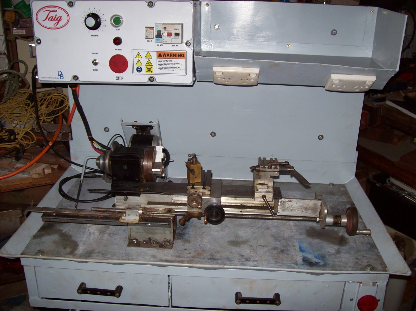
Figure 5 - the new cabinet with Taig lathe in place


Electrical highlights
300W DC PM motor driven via a PWM VSD (Pulse Width Modulated) (Variable Speed Drive)
NVR and E-stop safety circuitry (No-Volts Relay)
4 switched GPOs onboard


Powered from a single 240VAC IEC power cord


Figure 6 - electrical cabinet

Mechanical features
Metal cabinet with enough "meat" to permit drilling and tapping accessories anywhere I want.
Swarf tray with gate in floor
magnetic metal base for DTI, etc
motor mount has a "belt unloader"
All painted up in "Bender gray" except the 4mm thick metal baseplate

The motor mount is loosely based on the Nick Carter design, but modified for my purposes with a cam operated unloader mechanism.


Figure 7 - the motor mount in the "unloaded" position

The control panel represented an interesting amount of work which will be covered in greater detail later. one of the fun parts was the logos and labelling - the frustrating parts was doing the wiring to a suitable standard which permitted easy construction, and repairs.


Figure 8 - close up of control panel

In all, about one month's work over weekends, and the odd day here and there (mornings during shift rostered days.) - estimated total labour time would  be 100 hours
The wiring took about 3 days since I had to redo some of it when my neighbour offered some advice on how to make it better for someone else to fault find in.
Everything except the motor and some electrical components was either constructed, or salvaged - the out of pocket expenses were around $200, and a large chunk of that was for the power supply.

I will do up some articles which highlight the construction process, with focus on the various components/ skills, but in the mean time I'm going to enjoy using this "reborn" lathe.

Friday, April 9, 2010

Bender's foundations - feet, legs, base - part 1

The foundation, the base, what holds Bender up.

I started with the largest piece of scrap sheet I had which was 4mm thick. It's about 900x600mm (3' x2') and marked it up so Bender would be standing with his feet centered 150mm (6") back from the centre-line. I made him off-centre since I determined his center of gravity would always be forward of his center-line due to the positioning of his arms, the door being opened, and the weight offset in the head (weight of eyes, shroud).

I also decided his feet cups would not actually rest on the plate directly. I decided this based on trying to prevent rust from moisture being trapped there, and to give me the option of covering the base plate with sand, cement, or some other covering to disguise it. The gap under the foot cups is about 6mm (1/4"). So how are the feet attached to the base?

The foot cups are simply the tops of 9kg(20lb) NuSwift DCP extinguishers, appropriately cut, patched and positioned to make the feet. The NuSwifts used to have a large bronze valve at the very top containing the release disk, hose port, and carry handle. The valve casting screwed into the top of the extinguisher via a large bronze pressure fitting which was brazed inside the body of the extinguisher. In the above photo a gutted valve has been turned upside down and bolted to the base plate. A small piece of steel has been welded to the baseplate between the handle lugs to prevent the valve from turning on the retaining bolt. The foot cups are then simply screwed onto the valve from the underside with only the bolt and spacer protruding above the cup. By locking the rotation of the valve, and marking the feet ( The chalk "R" inside the cup) the feet can be repeatedly placed on the baseplate the exact same way.

The above two photos show my first attempts at making the legs from short sections of extinguishers cut and welded at angle to approximate the curved legs. - I know I could have made them straight like Simon did at asciimation, but I wanted to make mine curved since it seemed more natural and "in character". After many frustrating attempts at trying to make the legs from the extinguisher sections, I thought of a better way, and cut the old attempts away from the feet and pitched them in the trailer for the tip.


The new legs... "Captain Dan, you've got new legs" - sorry couldn't resist....
The new legs were made from some pipe I scored from some friends at work. Apparently it was leftover from some obscure job and didn't suit anything around the plant. It was an odd size - 83mm OD (about 3 1/2") and only 2 mm larger than my plans called for. I marked the centre-line of the pipe, and called that 12 o'clock. I then marked lines at 2 and 10 o'clock. this divided the circumference of the pipe into two sections, one of 60 degrees, the other of the remaining 300 degrees. I then marked out the regular segments based on the spacing being equal to the diameter. I had originally thought to have the welds visible for the legs and arms, but later ground them flush.
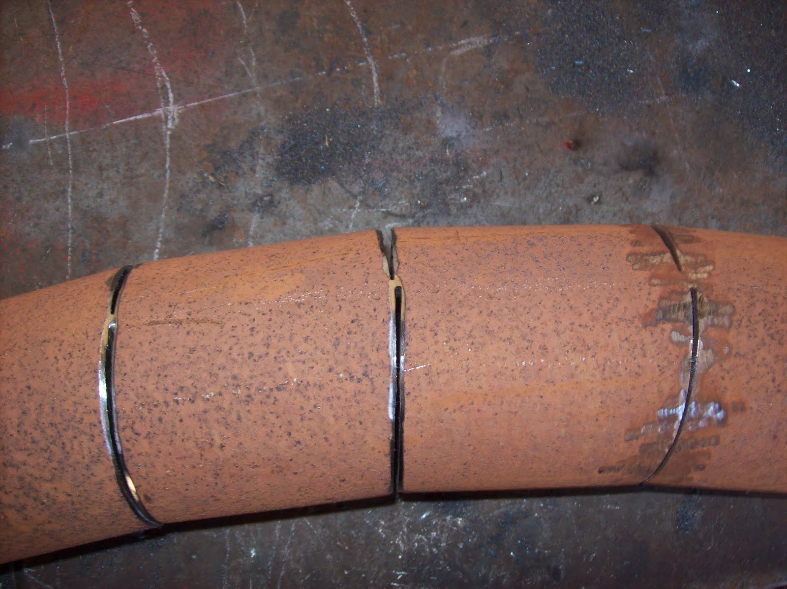
With the marks all in place, I used a 2.2mm cutting disk to cut the 300 degree segment lines. I then left about 1mm (1/16") of connected steel, and used a 1mm disk to cut the 60 degree segment lines. This allowed me to "bend" the pipe so the 2.2mm cuts closed on themselves, and the gaps at the 1mm cuts only marginally increased. The resulting curve is shown below, with some minor grinding to prepare for welding.


A note about my welding... I've been asked what kind of welder I have. It's a common cheap arc welder - 240VAC "buzz box" using 2.5mm SatinCraft welding rods. I'd love to have a MIG welder, but that will have to wait for another day. I did try learning how to use a MIG welder several years ago, but I'd got so used to controlling my arc by my own hand, I kept moving the handpiece and not compensating for the wirefeed. Learning to MIG is on the "to do" list, but a long way down whilst the stick welder does what I need.