Showing posts with label brass. Show all posts

Saturday, June 25, 2011

Field desk - Part 7 - Carry strap

I finished the field desk and took it for a walk up and down the driveway a few dozen times and decided that if I had to carry the field desk any significant distance, the handle would become uncomfortable quite quickly. I determined I'd need to fit a strap of some description...

I designed a few options based around a quick dis-connectable strap which would have been based on an inset plate, with a "key-hole" shaped hole which would have allowed a strap to be connected without load, and lock in place under load. I planned on making this from the brass strip I have, and make a mushroom post to enable this function. Easily within the scope of my skills and materials, but the more I looked at the idea, something just felt wrong about it - still haven't figured out what.
Figure 1 - Front view of desk with carry strap as if carried
Under further consideration, I figured it might be easier to make a strap which would fully support the desk from the bottom, and also the sides - the previously mentioned solution would have used the top edges of the sides to carry the weight. I designed a strap which essentially followed a path under the base, up each side, and up over my shoulder. A "waist" strap would go around the desk in the horizontal plane, and have a clasp to permit it to open on the door side.
A few lengths of salvaged seatbelt material, a clasp from an old salvaged life-jacket and about one hour on the sewing machine and this is the result...
Figure 2 - Side view of desk in carry strap as if carried
Since none of the lengths of seatbelt material were long enough, I made the bottom strap as one piece, and added a brass "adjuster" at each end to permit attachment and adjustment of the shoulder strap. These adjusters were made from (50x75x3mm) 2" x3" x 1/8" brass strip. A sliding dog was made from offcuts of the same strip brass.
Figure 3 - Front view, close up of clasp
A piece of scrap denim was sewed in behind the clasp to reduce it rubbing into the paintwork of the desk, and all sewing was done with over-sewn double runs, and polyester thread.
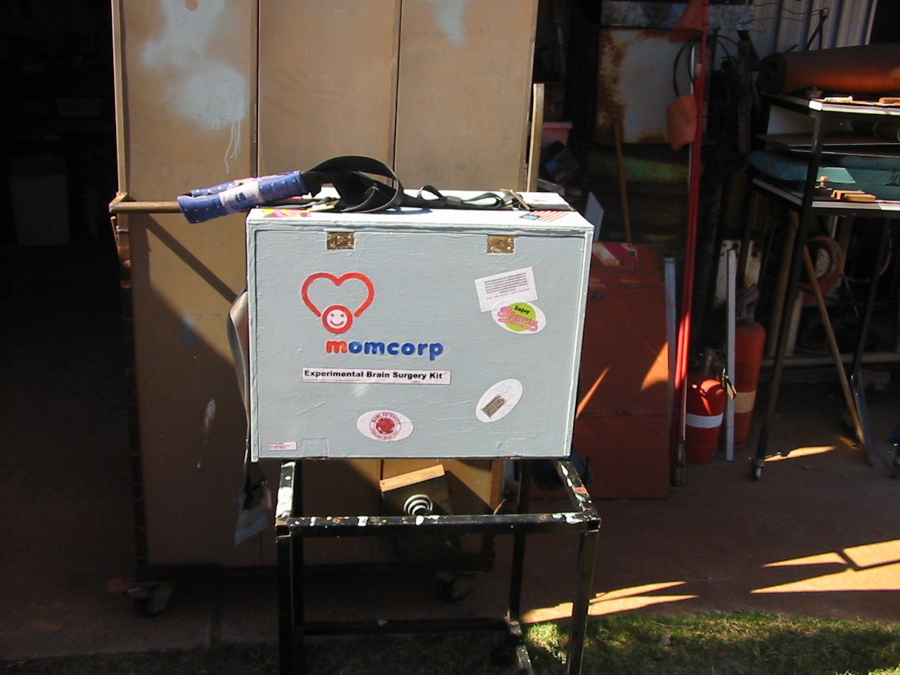
The strap can be left in place and the door easily lowered, or just as easily totally removed, and reinstalled when it's time to move the desk.
Figure 4 - Front view of desk with strap unloaded on top
When I collected the seatbelt material from the training cars (what was left of them) I found one car had those detachable seatbelt pads - Given the final weight of the filled and complete desk, I elected to place those seatbelt pads on the shoulder strap to even the load and reduce any chance of bruising from carrying the desk for a long time.
Figure 5 - Front view with clasp undone to permit door opening
A lesson learnt on this construction - when sewing seatbelt material, the upper thread tension on the sewing machine needs to be increased - otherwise the lower side threads all bunch up - my guess is the thickness and weave of the belting makes it harder for the thread to pull up enough under normal thread tension.
Figure 6 - Door open with DPScope on desk surface
The last photo is of the DPscope I purchased with some recognition money I recieved (a program they do at work to recognise efforts put in by staff) - The DPscope is a DSO scope which connectes to a PC via USB and has 2 channel capability. Since it only arrived yesterday, I haven't had time to play with it yet, but will do so over the next week - hopefully.

That is it for the strap - hopefully I won't need to carry it far that often, but now I can. I don't know what the next article sets will be - I've heaps of books to review, many projects in the WIP box (WIP = Work In Progress), and a lot on my plate outside the shed. This past week has been a series of quite long days, and in the next 2-3 weeks I hope it will bear fruit in many forms - the least of which will be my Cert 2 in Emergency Response... the rest - that's my secret for now.

Saturday, June 4, 2011

Field desk - part 2 - Hardware

Hardware fabrication


Hinges
Using the design I created, I needed to be able to remove the door to use as a work surface. I built two hinges from brass - 1/8"T x 2"W brass strip, and some brass rod salvaged from the spindle of an old household tap.
Figure 1 - Hinge materials
The hinges were patterned on a half barrel hinge style similar to those used on trailers for the tail gate - I choose that design so the door could be removed in a similar fashion.
Figure 2 - Hinges under construction - engaged
The spindle was cut and then turned in the lathe (Taig) to make the parts. Once made, the strip brass was cut and filed to suit the parts, and then all pieces soldered together.
Figure 3 - Hinges under construction - released
Once the hinges were finished, I inlaid them into the floor and door of the desk, and rebated in the backing plates on the reverse side of these surfaces. The screws securing the hardware are all 3/16" UNC (10-24 for our US cousins) into a nut plate on the reverse side.
Figure 4 - Hinges fitted - engaged
A notch has been cut in the RH side panel to permit the door to be removed similar to a trailer tailgate.
Figure 5 - hinges fitted - door released
Locks
Next thing to make was the locks. The requirements on the locks was that the door had to be perfectly flat on both sides - the outside so it would lay on a table top and not scratch the table, the inner surface needs to be flat so it can form the working surface when I'm using the desk.
I planned on making disc-locks, but after reviewing my stock of materials, came to the conclusion that cam locks would be the design. I did not have much in the way of 1/2" diameter brass rod, so I decided to use a cartridge case (.243 Win) to form the shaft. (I have a stash of around 20 of these cartridge cases which were given to me for scrap brass). The cam plate was roughly made up, and then soldered to the cartridge case at the appropriate height to permit the base of the cartridge to be used as actuating surface outside the door.
Figure 6 - Cam lock under construction
The front and back plates were made up, and the lock assembled. Only once assembled was the cam shaped to its final length, with some easing to improve its alignment when turned. The base of the cartridge was spot-drilled to match the "keys" I made - basically a small pin-wrench.
Figure 7 - Pin-wrench "key" under construction
The pin wrench started life as one of those promotional key-chain bottle openers, but after cutting and drilling a pair of nails were driven in and cut and filed to make the pin-wrenches. I made 2 of the keys so I have a spare.
Figure 8 - Finished lock - in locked position
Once the front and back plates were completed, a top plate was made and soldered to the front plate. Clearance slots for the cam operation was made, and suitably relieved for easy use. The holes in the lock were drilled to indicate the lock status - vertical holes indicate the lock is "locked", horizontal holes indicate unlocked - there is only 90 degrees of movement in the lock mechanism.
Figure 9 - Finished lock in unlocked position
Door opening mechanism - The Pusher
Since the door has to be perfectly flat on both sides, there is no handle. I considered a flip out handle, I considered simply drilling a hole to poke my finger through - both ideas had aspects which did not appeal to my sense of this project... What I really needed was something inside the desk to push the door out once the locks were released... What I came up with was "the pusher".
The pusher is nothing more than a simple spring loaded detent plunger - but instead of pressing into a detent hole, it simply pushes the door away from the locked position by about 1/2" - more than enough to get my finger on to lower the door to the table top. The pusher uses another .243" cartridge casing for the spring holder, and the plunger is made from more tap spindle stock. Who knows where the spring came from, I've boxes of salvaged "useful junk" which gets pawed through when I do jobs like this.
Figure 10 - Pusher components
The spring casing is rebated into the riser, and the cover plate relieved into the edge so there is no protrusion other than the plunger.
Figure 11 - Pusher spring casing installed
This piece of hardware is the only one secured with normal wood screws into wood - all others use the nut-plate method described in the hinges. The screws into timber should be able to hold the minor force of the spring at the end of its travel.
Figure 12 - Pusher installation nearly complete
Once the locks are unlocked, the pusher moves the door about 3/4" if the LHS doesn't grab (that bowed panel as mentioned when I built the carcass), 1/2" if it does rub... either way I can still open the door easily.
Figure 13 - Result of pusher on unlocked door
Handle
The other piece of hardware to build was the handle. Most of my toolboxes have handles which protrude on the lid - making it nearly impossible to stack things on top. Given the intended use of this desk is in a "accommodation camp" where I may need to stack a laptop, or books on top, I was insistent that the handle design had to leave the top surface perfectly flat. The ideal scenario would have been to use the folding handle from the top of a 7.62 x 51mm ammo can - but I couldn't find any. I did not trust my skills to make one, so I looked at every box and case I owned looking for a low profile handle - I stole this idea off an industrial first-aid cabinet.

Figure 14 - Handle components
The basic strap (handle) is made from 2 layers of pallet strapping - the 3/4" wide blue/black metal banding you find on pallets of bricks and other heavy things. I drilled and slotted it, then shrunk two layers of heat-shrink tuning over it to make the handle comfortable. I then made a pair of brass "sockets" which hold the handle, and allow it to slide in it slot for extending under weight, or retracting when not in use. I made the top plates for the sockets larger than required and drilled 2 large holes in each for attaching labels (addressing, or shipping labels).
Figure 15 - Assembled handle
Since I'd already glued the carcass together (my enthusiasm bit me hard there) I had to make my own "T-Nuts" to engage from the underside. Basically cylindrical spigots soldered to shim brass which were then friction fitted into holes in the timber. I wasn't feeling overly confident in the solder joints, so I backed the nuts up with some Loctite CA glue. If the nuts pull through, I'll have to look at redesigning the handle nuts, but so far OK.

Figure 16 - Completed field desk with all hardware
Since nothing was rebated in, and the finished handle is proud by 1/4", I still had protrusion to deal with, so the only quick answer was to cut an overlay board of 1/4" plywood and screw it on top to raise the surface of the top around the handle. - Not ideal, but I'd rather do that with 1/4" ply than the 1/2" ply I'd have needed for the commercial handle the local hardware store had. (trying to keep the weight down)
The additional sheet can be seen in Figures 16 and 17. It comprises some 1/4" (6mm) plywood, and an interposing sheet of cardboard (edges covered with masking tape) - this effectively recesses the handle, with minimal weight gains.
Figure 17 - Demonstrating use of tag holes in handle

All screws for the hardware had to be cut down in length so there was no protrusion to scratch the tabletop. A dab of thread-locker will be applied during final assembly just to ensure they don't come loose during travelling.

Still to come:
Electrical section
Trays and containers
finishing

- apologies for the number of photos  - next time I'll do this as two articles.

Saturday, May 14, 2011

Dividing Head for Taig (and others) - Part 4 - sector arms, plunger, etc

Last article for the Dividing head.... What's left to discuss?
Sector arms
Plunger arm
Retaining Knob and spacers


Sector arms
The sector arms are patterned on the arm design from Tony Jeffree's website. The arms were first patterned out in cardboard, then cut out using a hacksaw, files, and drills.
Figure 1 - Sector arms with locking screw
The lower arm is then soft-soldered to a brass boss which protrudes to form a spigot for the upper arm. A screw has been drilled and threaded so it fully engages in the boss, but it's head overlaps the moving arm. A small brass cylinder was made to concentrate/ exaggerate the clamping force from the screw head.
In normal operation the screw is loosened by about 1 turn, and the upper arm can rotate freely on the spigot of the lower arm, once set at the appropriate arc angle (hole spacing), the screw is simply re-tightened to lock the arms in positions relative to each other. Both arms are still able to rotate as an assembly on the spigot of the plate carrier.
Figure 2 - Sector arms on plate retainer
A cover, which is actually a spacer, sits over the arm assembly in use, but serves no functional purpose other than to increase the distance between the arm, and the surface of the division plate.
Not long after starting to use this dividing head, I found the tips of the arms were difficult to operate if they crossed each other - kinda like trying to open scissors by using the tips... To alleviate that issue I turned the tip of the upper arm upwards to form a handle. I could have added a nice little knob, but I was worried about the extra weight on the slender arm.
Figure 3 - Spacer cover on sector arms

Plunger arm
The plunger arm - the arm which actually rotates the worm, is made of 1/4" thick brass strip. A slot (1/4" wide) was made through the middle by the use of chain drilling, and filing. This slot engages the flats filed on the worm shaft. A brass plunger mechanism was fabricated and the body soft-soldered to the arm.
The slot was made so the division plates could have multiple rows of holes, although typically I use only 3 rows of holes per plate at most.
Figure 4 - Plunger arm fitted to worm shaft

One problem I have with this plunger is that the threaded portion which holds the shaft and handle together will sometimes spin undone whilst using the knob for rotating the worm. I'll remember to dab a drop of superglue in there one day, but until then I remember to tighten the threaded joint before use.

Figure 5 - plunger arm secured by retaining knob
Retaining Knob and spacers
The retaining knob is simply a brass turned object, and my first attempt at knurling. The picture makes it look better than it actually is... the knob won't roll of the table because there is a flat spot on the bottom where the knurling "crunched up" - I can't explain why it happened, and I've since tried to rebuild the scissor knurler, but I keep having issues there.
Figure 6 - Retaining knob in profile
As mentioned with the sector arms, there is a cover which acts to space up the plunger arm. There is another spacer which sits above the arm to space the retaining knob. With both spacers in their correct locations, the arm is essentially clamped to the worm shaft not only by the slot, but also by the clamping of the spacers. It basically removes any clamping effects from the knob on the sector arms, since if I place the upper spacer in the wrong position (under the plunger arm) it will attempt to turn the sector arms when I operate the worm.
Figure 7 - Spacer ring above sector arm

Most of the brass was from the scrap merchant I mentioned in my previous articles, but the brass sheet for the sector arms was bought as scrap from the local radiator place (along with a clapped out 8" bench grinder which only needed $12 worth of bearings), and the brass for the plunger arm was purchased from the scrap bin of a local fabrication mob (NOT cheap)


 As previously mentioned, the spigot at the rear of the dividing head body permits the plate/worm assembly to rotated through about 180 degrees allowing the dividing head to be used vertically, or horizontally and still have the sector arms, division plate, plunger arm facing the operator.
Figure 8 - Plate assembly rotated 45 degrees to illustrate movement


That's about it for the Dividing head.. it's been used on and off over the years for a few jobs and will continue to be used for many more. The most recent job was making up a wrench called a "Torx-plus" so we could access the internals of a harddrive enclosure. The Torx-plus is a 5 lobed version of the more common 6 lobed "torx" bit. I made the bit  by drilling holes in the end of a piece of steel shaft to create 5 holes on the appropriate PCD, and then turned the holes away to only leave half the hole. The metal between each hole was used left in place to form the 5 lobes needed to turn the screws out of the enclosure.

I'll have to sit down one day and see if I can improve the design around the sector arms and plunger - it works, now, but it does need some improvement so the spacers aren't necessary - they are a pain if the top one gets put in out of sequence (below the plunger arm).

The field desk is progressing along, and will be the next article series at this stage. I've designed the locks and latch, and have commenced designing the hinges, support arms, lighting and handle. Somewhere in all that I'll need to decide what colour to paint it. This week I have jury duty, so it's possible I may get an hour each arfternoon/evening to work on the hardware.. here's hoping.

Sunday, May 1, 2011

Third hand - electronics tool

I have some work on the horizon where I may be away from my shed for periods of time. It's still up in the air, in the hands of Heavenly Father, managers, and others. In the meantime I'm getting things ready...

One of the things which I'm going to need is a portable electronics kit. My current setup is based on an old fishing box full of tools, and several tubs full of parts in various trays, etc. I've decided the best method to deal with the proposed situation will be a "field desk" with the minimum of what I require, and a contained work area.

The desk will be covered in another article series, but this article introduces the first tool made for the field desk... the third hand.


Figure 1 - third-hand in use - salvaged PCB from old fire-panel

For those who aren't familiar with the term, a "third hand" is simply a means of holding something whilst keeping your own two hand free. I used a third hand whilst at uni and found the design quite good and duplicated the essential features here.

There are other designs out there. most work on the principle of a heavy weighted base for stability, and then posable arms terminated with clamps. The one I used at uni (made by the lab techs there) used lightweight materials and a door hinge for the "pos-ability".

The only concession from their design to mine was that mine had to be collapsible so it took up less space in the field desk. The original unit did not come apart, and as such occupied a space of 200 x 125 x 150mm (8"x 5" x 6") - this design occupies the same space in use, but folds down to 180 x 125 x 35mm (7" x 5" x 1 1/2") for storage.


Figure 2 - flipped to other side for soldering work.

Since the unit can flip too far in one direction, a small piece of perspex can be inserted to limit the travel of the hinge as shown in Figure 3.


Figure 3 - inserted piece of perspex limits hinge travel.

I used some of the perspex I salvaged from some shop shelving, and cut it to utilise the existing lip which was on it.
A pair of pieces were cut to match and support the hinge, and this pair were then drilled to sit between the two halves of the base.
Some bolts were modified to make them "tool-less" by soldering their heads into a brass piece which had a square washer affixed - I'd have preferred wing nuts and wing-bolts but didn't have any.

The clamp which supports the PCB is simply one leaf of the hinge, and a piece of aluminium which is made from a drawer divider. The cranked over fold is used to form one part of a toe-clamp, and to provide clearance over the nut which holds the bolt in place.
A stiffening plate is captured under these bolts to provide more gripping surface. Again due to my lack of wingnuts I made up some nuts using brass. The brass used for making the wing nuts (and bolts) is from discarded tap spindles, the sheet from an old door strip.


Figure 4 - cross- view of PCB clamp with perspex gripped for illustrative purposes


Figure 5 - View of base assembled showing component parts.


Figure 6 - dis-assembled third-hand showing all parts

Soldering is simply done with a propane torch, using "Baker's fluid" as the flux, with normal 60/40 soft solder. Only the minimal amount of solder is applied, and excess is trimmed away to prevent absorption through normal use.

Figure 7 - Third-hand collapsed ready to be stowed

The field desk will be built with PICAXE projects in mind. I have a few which I need to get completed, and since all I can have at the camp is books, and minor electronics (no Lathe or other powertools) I figure this will make good use of what spare time I have.
Even if this proposed change falls in a heap, the investment in making this desk, and associated tools will still benefit my electronics hobby.

DTI Mag-Base repairs

a while ago I discussed a broken mag-base I salvaged from being tossed out. That article discussed the dis-assembly of the mag base.

In an effort to get the "To Do List" a little smaller I finished off the repairs to the indicator base.
I used the spindle from a discarded tap to make up an actuating system for rotating the mag-core. I simply filed the required square shape into the section which used to hold the jump valve.
The threads which actuate the original tap were turned away, and replaced with a parallel section.


Figure 1 - Tap spindle filed to square

A plastic bush was turned to locate the mag-core inside the void in the mag-base, and to provide support to the spindle. The plastic was from a sheet of 25mm (1") thick plastic (nylon I suspect) that I rescued from a bin. A suitable square was cut from one corner, and a 10mm hole drilled through it. A 10mm bolt and nut were inserted, tightened up, and used as an arbor for the turning. Whatever the plastic was, it certainly was "stringy" in the swarf.


Figure 2 - Commencing turning the plastic bushing

A brass indicator/ handle was made from an old brass fitting, and some sheet brass, and soldered together.


Figure 3 - Actuating knob and pointer prior to soldering


The spindle was designed to pass through the front plate which was made from some brass strip. The front plate is shown on the RHS of the exploded view below (Figure 4)


Figure 4 - exploded view of mag-base

In the above exploded view, everything to the right of the magnetic core, and everything above the magnetic base were made from salvaged materials.

The magnetic core was filled back to remove the old damaged paint, and engraving markings. A few minor dings were cleaned up, and then the base was primed with cold-gal paint (Zinc-it) then followed up with a couple of light coats of Silver Hammer finish paint.

Upon assembly it was deemed too difficult to re-drill the existing holes to their proper spots, so new holes were drilled for securing the face plate.


Figure 5 - the magnetic core in the base with the spindle and bushing in place.


Figure 6 - The mag-base assembled

One of the salvaged lengths of steel from a gas strut was used to make the mast on this base - although a brass socket and washer was turned from an old extinguisher part (CO2 nozzle) to stiffen the joint instead of simply using the M8 thread.


Figure 7 - The  mast on the mag-base made from gas strut

An offcut of the gas strut remains, being about 125mm (5") long which will most likely be used for making one of the connecting rods.


Figure 8 - The completed mag-base next to the Taig lathe.

I've possibly made the mast too tall, but standing next to the Taig lathe, it has sufficient height to ensure access to anything I put in the lathe, or the vertical slide. I've yet to make the other smaller poles, joiners, and DTI connectors, but that should be fairly easy to do over the next few weeks.

That said, guess who's added more projects to the list... You'd think I'd have learnt by now, or maybe it's my curse (or is it blessing) to always have more jobs than hours to complete them...


I did up a quick explanation of how a mag-base works for someone, and decided to include it here in case anyone else needs to know how they work. I've since cleaned it up and converted it to a JPG.


Figure 9 - Theory of operation - magnetic stand

Monday, November 1, 2010

Santa costume - belt - part 5

Santa's belt

The idea was to use some near new automotive seatbelt material taken from one of the cars we'd cut up in training. Based on the that material, I designed a large brass buckle to suit.

Since I didn't have any suitable material to make the whole buckle from one piece, I decided to use some thin brass shim stock for the face of the buckle, and build the bulk of the buckle from thicker, but smaller brass material. Why couldn't I cast a buckle??? That's a story for another day....grumble and mutter.

I cut up the shim stock sheet to give me the shape I wanted, plus folding pieces to cover the joints.


Figure 1 - brass shim stock, and other material

I then cut up some 3/16 x 2" strip to give me the shapes I needed to fill in the back of the buckle. I then folded the shim stock up over the inserted pieces, and sweated it all together with soft solder. My torch is a Primus (Seivert) propane torch with a pencil tip.


Figure 2 - cutting the shim stock with a jeweller's saw


Figure 3- folding in the pieces prior to soldering


Once finished I tested the buckle only to find it didn't "grip" the material well enough to give me confidence. I considered adding a small barb in the buckle so it would grip, but figured it might pose a hazard. Determining the issue resulted from the excess clearance in the buckle openings, I drilled the buckle in four places and inserted some 1/16" stainless steel wire to close up the gaps. In fact it allowed me to double the material through the buckle, adding security and improving the appearance. The wire was cut from an antistatic dissipator from an old CO2 fire extinguisher


Figure 4- Buckle - Mk 1 - not suitable


Figure 5. Buckle Mk2 - with wires inserted


Figure 6. The good buckle threaded onto the belt material

I also made a smaller version of the buckle - reminiscent of a military buckle for capturing the excess belt length (tail as it were) - together they both hold the belt up nicely, and I need not fear the jacket coming open. (I started the smaller buckle while trying to think of a way to salvage the first buckle - thankfully I was blessed with some inspiration there... it would have been a shame to waste it.)


Figure 7. Both buckles on the raw material

Once it was all together, I noticed the seatbelt material would shine in certain light, and it looked distracting. To make the belt more consistent, I over-sewed it with 3 layers of black poly-cotton, and sewed rows of stitching the full length on 6mm (1/4") centres. This added a nice touch to the fabric, and allowed me to taper the open end of the belt making it easier to thread and prevent fraying.

Once the brass was polished up, the belt came out wonderful... the buckle adds a bit of weight, in fact the entire belt weighs in at around 1kg (~ 2 lbs)

Next installment - the hats.