Showing posts with label perspex. Show all posts

Sunday, May 1, 2011

Third hand - electronics tool

I have some work on the horizon where I may be away from my shed for periods of time. It's still up in the air, in the hands of Heavenly Father, managers, and others. In the meantime I'm getting things ready...

One of the things which I'm going to need is a portable electronics kit. My current setup is based on an old fishing box full of tools, and several tubs full of parts in various trays, etc. I've decided the best method to deal with the proposed situation will be a "field desk" with the minimum of what I require, and a contained work area.

The desk will be covered in another article series, but this article introduces the first tool made for the field desk... the third hand.


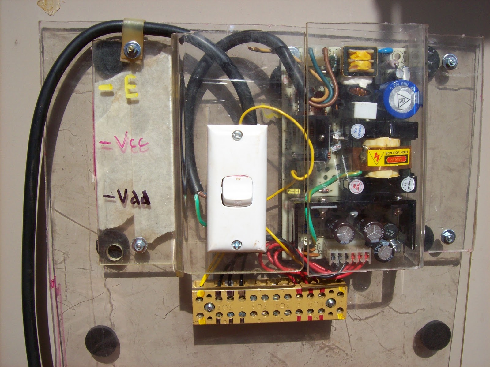
Figure 1 - third-hand in use - salvaged PCB from old fire-panel

For those who aren't familiar with the term, a "third hand" is simply a means of holding something whilst keeping your own two hand free. I used a third hand whilst at uni and found the design quite good and duplicated the essential features here.

There are other designs out there. most work on the principle of a heavy weighted base for stability, and then posable arms terminated with clamps. The one I used at uni (made by the lab techs there) used lightweight materials and a door hinge for the "pos-ability".

The only concession from their design to mine was that mine had to be collapsible so it took up less space in the field desk. The original unit did not come apart, and as such occupied a space of 200 x 125 x 150mm (8"x 5" x 6") - this design occupies the same space in use, but folds down to 180 x 125 x 35mm (7" x 5" x 1 1/2") for storage.


Figure 2 - flipped to other side for soldering work.

Since the unit can flip too far in one direction, a small piece of perspex can be inserted to limit the travel of the hinge as shown in Figure 3.


Figure 3 - inserted piece of perspex limits hinge travel.

I used some of the perspex I salvaged from some shop shelving, and cut it to utilise the existing lip which was on it.
A pair of pieces were cut to match and support the hinge, and this pair were then drilled to sit between the two halves of the base.
Some bolts were modified to make them "tool-less" by soldering their heads into a brass piece which had a square washer affixed - I'd have preferred wing nuts and wing-bolts but didn't have any.

The clamp which supports the PCB is simply one leaf of the hinge, and a piece of aluminium which is made from a drawer divider. The cranked over fold is used to form one part of a toe-clamp, and to provide clearance over the nut which holds the bolt in place.
A stiffening plate is captured under these bolts to provide more gripping surface. Again due to my lack of wingnuts I made up some nuts using brass. The brass used for making the wing nuts (and bolts) is from discarded tap spindles, the sheet from an old door strip.


Figure 4 - cross- view of PCB clamp with perspex gripped for illustrative purposes


Figure 5 - View of base assembled showing component parts.


Figure 6 - dis-assembled third-hand showing all parts

Soldering is simply done with a propane torch, using "Baker's fluid" as the flux, with normal 60/40 soft solder. Only the minimal amount of solder is applied, and excess is trimmed away to prevent absorption through normal use.

Figure 7 - Third-hand collapsed ready to be stowed

The field desk will be built with PICAXE projects in mind. I have a few which I need to get completed, and since all I can have at the camp is books, and minor electronics (no Lathe or other powertools) I figure this will make good use of what spare time I have.
Even if this proposed change falls in a heap, the investment in making this desk, and associated tools will still benefit my electronics hobby.

Monday, April 25, 2011

Taig lathe cabinet -control panel and switches

To conclude the discussion about the construction of the lathe cabinet, I'll now cover the switches, and finer points of the control panel

In my day job (which seems to cover days, nights, weekends, and other times as well... but that's another story) I am quite familiar with industrial emergency switches - aka E-Stops, or "Lock off stops" (LOS)
Industrial E-stops tend to have replaceable contact blocks which bolt to the back of the switch mechanism, and these contact blocks can be double sided, stack-able, and able to be used in a variety of configurations to suit the control need.
I have one or two of these switches which I've salvaged from discarded equipment, but the contact blocks add at least 40mm (1 1/2") of depth behind the faceplate - unsuitable given the space constraints at the tail stock.


Figure 1 - Two N/C switches with perspex circles glued on

Since I only had 18mm (3/4") behind the switch at the tail-stock, I decided to build my own e-stop switch until a commercial alternative presents itself. I purchased a number of N/C (Normally Closed) momentary push-button switches from one of the e-bay stores (Virtual village from memory) to use as e-stops.
I also purchased some N/O (Normally Open) momentary push-button switches as well... for some reason the N/C switches were only available in Yellow, and the N/C in Red - no matter.

I then cut out some suitable sized circles of perspex (Hole-saw with the pilot drill removed - whole job done by clamping in a drill press) and glued the circles on the button face using a cyano-acrylate based glue (Loctite Prism, or some other form of "super glue" - aka "crazy glue")


Figure 2 - N/O switch with smaller perspex circle glued on, next to bored out PET bottle cap


The two e-stops were then painted red using a sheet of paper glued over the perspex, and paint sprayed onto that. The paper makes the perspex opaque, and helps it take the paint better.

A similar method was used to make the button on the N/O switch slightly larger, and painted green.

The N/O button was to become the "Start" button, and as such I felt should be shrouded to prevent accidental activation. I could have made a nice professional shroud using pipe with an end cap soldered in and bored out, or I could simply grab a lid from a PET soft-drink bottle and bore it out to match the switch body.


Figure 3 - Test fit of "Start" button in shroud - using tail-stock mini-panel for support.


The panel was marked out and drilled for all switches prior to painting, and the back was marked up to make wiring easier.

The PWM circuit (commercial kit from Oatley electronics - Kit K252 ) was grafted on to a surplus Pentium heat-sink, which was then screwed to the top inner surface of the control panel so the fan blew directly on it. The on-board potentiometer was replaced with a wired external unit which is accessible as the speed control knob on the control panel. I had a few hiccups with the kit, but not as a result of any problem of Oatley's... All resolved now, but issues included one terminal block cracking when tightened up, and a dodgy soldering job on one oscillator pin.


Figure 4 - Back of control panel with PWM circuit assembly resting on it

I used some of my salvaged spiral wrap for the cabling - turned out to be a disaster since the wrap was so old the plastic was brittle. I had a chat with Wayne at Rexel and bought some more.. cheap chinese stuff instead of the the Cabac brand we use at work, but certainly much cheaper... and it seems OK for my use.


Figure 5 - Control panel front view prior to painting or labelling.

The cabling of the control panel was covered in my previous post and will not be repeated.
The control panel was simply painted "Bender grey" along with all the panel work and a label was made up.
The label was made from creating the text and dial markings, warnings etc  in Paint, and then assembling them on a page and printing it out. I then cut the paper up, and rearranged them to match a tracing already done from the finished panel. Securing screws, holes for breakers, relays, controls etc were marked in and the text placed around them. Once completed, the finished sheet was then placed through a colour photocopier and trimmed for effect. A pass through a laminator and re-trimmed and it was ready to be glued to the control panel. Peter Homman described a similar method for the prototyping of control panels for products, including membrane switches - it's a good idea I was grateful to be able to learn from.


Figure 6 - completed control panel with paint and labelling


A quick few notes:
  • I won't be adding anything more to this Taig lathe cabinet article series unless someone needs clarification on something... use the "contact page" to send through any questions.
  • I don't plan on offering any drawings or plans.. I can take a few more photos, but that'll be only if requested.
  • If you're in Australia... look at Oatley for cheap kits and other interesting bits and pieces. The motor currently fitted to this lathe is one of their 300W scooter motors. Since there isn't a cheap source of treadmill motors in oz (similar to the big surplus stores in USA) this is a good alternative. I've bought from Oatley over the years and found their prices and range reasonably good for a number of products.

Lastly... what would I do differently if I repeated this project?
  • Use a finger brake for the panel work for a neater finish
  • Make the swarf gate bigger, and the swarf container smaller (so an industrial E-stop with contact block can fit)
  • Use more flexible cable for the 20A DC wiring
  • Add a separate circuit breaker to  allow the motor drive (PSU, and PWM, etc) and the fan to be operated separate from the supply to the GPOs
In the words of Porky Pig, "That's all folks"... next post will be back on one of the many other projects I'm trying to get off my "to do list"

Saturday, January 15, 2011

shed PC cabinet, and electronics test gear

another set of projects!!! - Yes I know - got more than enough on my plate as it is, but it is related (see end of this post)

I needed a PC in the shed for programming work. Given the lack of space, the easiest thing to do was put the PC in a wheel-able cabinet, and packaged in such a way to permit it to be collapsed as small as possible.

I'd rescued an old 3M overhead projector a couple of years ago, and the wheeled stand it came on... This stand, with a few modifications, became the PC cabinet.

The original stand had a top which was set approx 6" (150mm) under the level of the top vertical posts, and the 2 flip out leaves attached to the posts. I raised the top shelf to line up with the posts, and then closed in the underside on 3 sides with some old sheet metal.  I took another piece of metal to work and bent it up to make a door for the fourth side.


The "front door" of the PC cabinet is the grey sheet of metal on the RHS of the picture - with black cloth tape covering the cut edges for hand protection.


The above photo shows the LHS leaf in the raised position - whereas the other photos in this article show both as lowered.

The PC is an antique (old celeron from memory) but it does what I need (runs the PICAXE suite of software). Network is accessible (if I run out the 15m patch lead) and the speakers, mouse and keyboard cabling is wrapped in a spiral wrap and pinned under the top shelf.

Currently (due to other projects) the most this PC does is play music for the shed area - the programming has been on hold for a few weeks now due to other commitments.


As part of the PICAXE work, I needed to rig up a 5VDC power supply for the breadboard and other circuit prototypes. Digging through my boxes of salvaged gear I found a near new 5VDC SMPSU. Using some scrap pexiglass, I fashioned up a board with the SMPSU encapsulated at the top. The scrap pexiglass had some bends in it already, and I used them to form the cover for the 240VAC section, and to mount the power switch.


It was a simple case of then bringing the 5VDC and COM rails out to the prototyping area by means of the terminal block. I also brought the mains Earth out as well. The colour code for the terminal positions is shown on the LHS of the cover.
LRF are applied on the bottom of the unit to stop the fixing screws from scratching up the top of the cabinet.


The unit fits nicely in the box with the other electronics bits.


Why PICAXE?
I needed something, and I was so out of date with my previous experience (6502, 8086, pic16f84) that I asked on the newsgroups what was the best to come back in with... the suggestions included Arduino and other systems, but PICAXE came through loud and clear as suited for what I'm trying to do...
I've a project to help someone who's eyesight is going. He's a machinist who's finding it hard to use a standard dividing head - I can't afford a "DivisionMaster" (excellent product designed by Tony Jeffree) so I'll try and build my own version (with several features not in the original - suited to the user's tasks) and bring my skills back up at the same time.
That is the story of my life so far - get an idea to do something, identify pre-requisite equipment and skills, acquire those, find there are more needed, etc ad nauseum.
Kinda the model engineer creed - "Build a jig to build a tool, to build a jig, to build a tool, to build a jig to build a project". In my case the lathe was bought to build a micro hybrid rocket motor, but the lathe needed parts so I started building parts, which meant I needed the furnace, which meant I needed to learn.... and on the story goes.
Don't take the above as a complaint - by the time I build that motor I'll have a fully equipped workshop, an amazing set of skills, and a very diverse set of experience - all I need is time... and patience... and space for junk... and money for bits...       :)