Showing posts with label cabinet. Show all posts

Monday, May 30, 2011

Field desk - part 1 - cabinet

Construction of the field desk

I have need for an electronics tool and experimentation kit which is self contained. I looked around on the internet for some ideas, but failed to find anything which suited my needs, or seemed practical for my planned budget.
The military used to use field desks (you occasionally see one in the old episodes of M*A*S*H if you want to see an example of a real one) and I thought that would make a good starting point for a design.

I googled (is that a real word yet?) "field desk plans" and found some dimensions from early American history re-enactors and museums. Most centered on dimensions of 24"W x 18"H x 10"D (nominally 600mmW x 450mmH x 250mmD) and that seemed like a reasonable size for my intended purposes.
Whilst planning the cutting for the timber I had, I decided to use an external depth of 12" (nominally 300mm) instead of the original 10" mentioned previously due to the depth of the plastic containers I am planning to use.
My timber was the remains of a UPS packing crate which I salvaged from a job about 2-3 years ago. The timber from the sides of the crate was 6mm (1/4") plywood, and the side which doubled as a ramp was 10mm (3/8") plywood. I drew up some plans and cutting lists using the 10mm ply for the top, bottom, riser, back and sides. I planned on using 6mm ply for the shelves, and some 12mm (1/2") plywood for the front. Due to a cutting error I ended up having to use some of the 12mm ply for the sides as well.
Figure 1 - Raw plywood material

Figure 2 - Cut into basic panels

After marking the timber to the largest finished dimension for each panel, I cut the panels out using a circular saw.
The rough panels were then marked up with the slots, dovetails, etc which were cut in using a jigsaw, hacksaw, and portable drill (the drill was used to start the slots for the finger joints. All external joints were made as dovetail joints to help the box stay together, whilst the internal joints (supporting the shelves) were made as finger joints (tab and slot).
Figure 3 - partially assembled carcass

During the construction I would clip the unit together to mark up the next panel - for some reason I got confuzzled at the end of the first day and assembled the desk with one piece reversed. This then meant the finished carcass went together upside down, and mirrored. Thankfully the photos I'd taken earlier in the day were able to be used to show me the correct orientation of the pieces, and allowed me to assemble it correctly the following day. Being right-handed, I really wanted the section for power to be on the RHS.

Figure 4 - Carcass assembled, but with pieces mirrored by accident - rear view
The back was marked up for dovetails and slots, then cut and fitted.

Figure 5 - Back panel marked up and cut for dovetails and finger joints.

Once happy with the finished carcass, I dismantled it and sanded all panels before assembling with construction adhesive (aka "Liquid nails") and PVA glue.


Figure 6 - Back panel in place on carcass of field desk, shelves not in place.

The front door was then cut and tested for fit. I found a slight bow in the LHS side panel - I'm still trying to determine if I can remove it,or if I will need to alter the door slightly to compensate. UPDATE - I modified the door slightly by allowing a slight amount of slack in the hinges, and put a heavy chamfer on the inner edges of the door, this allows the door to close and adjust it's centre based on the 1-2mm bow in the LHS panel.

Figure 7 - Field desk with shelves filled with sample material

Whilst the glue dried, I commenced work on building the hardware... hinges, catches, etc.

Next articles will include:
Hardware - hinges, catches, etc
Electrical - Lighting, PSU, etc
Finishing - Painting, trim, etc

Since I didn't get much done last week on the desk, I'm hoping to complete it over the next two weeks or so.

Monday, March 7, 2011

Taig lathe cabinet - completed

Today I took advantage of some time away from work during the public holiday to bolt the Taig lathe to the new stand.

Some history...

Figure 1 - original lathe stand

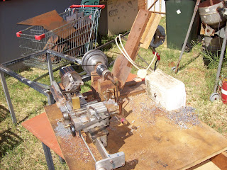
I bought the original Taig lathe from an amateur pyrotechnician in Brisbane in 2001 (or was it 2000?) The motor which came with it was a salvaged unit from a washing machine.


I modified the motor mount to retain the pillow block and 1/2" shaft, but mounted the motor and jackshaft on a set of sliding mounts which gave me a clutch in the form of a "belt unloader".


Figure 2 - motor mount and jackshaft on sliding mechanism

I put a drawer underneath the 18mm (3/4") MDF top sheet and used it this way ever since. In the meanwhile a removalist broke the jackshaft mounts, the motor board started a gradual twist (compensated for by inserting popsticks under the motor mounting), and the bearings in the motor started to fail.


Figure 3 - tail stock view of old stand

The motor controls (on-off switch) is mounted in the front of the white icecream container screwed to the baseboard - inside the icecream container is the start capacitor and the wiring out to the motor. - real high tech.

Over the past 5 years I commenced modifying the lathe by adding a leadscrew and halfnuts, converting the tool post and tail stock socket screws to thumb bolts, and building accessories.


Figure 4 - the conversion of socket screws to thumb bolts

So after essentially 10 years, this 12-14 year old lathe is getting a new cabinet and drive

That was the past - now here is the future...

Figure 5 - the new cabinet with Taig lathe in place


Electrical highlights
300W DC PM motor driven via a PWM VSD (Pulse Width Modulated) (Variable Speed Drive)
NVR and E-stop safety circuitry (No-Volts Relay)
4 switched GPOs onboard


Powered from a single 240VAC IEC power cord


Figure 6 - electrical cabinet

Mechanical features
Metal cabinet with enough "meat" to permit drilling and tapping accessories anywhere I want.
Swarf tray with gate in floor
magnetic metal base for DTI, etc
motor mount has a "belt unloader"
All painted up in "Bender gray" except the 4mm thick metal baseplate

The motor mount is loosely based on the Nick Carter design, but modified for my purposes with a cam operated unloader mechanism.


Figure 7 - the motor mount in the "unloaded" position

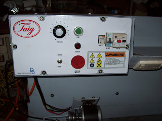
The control panel represented an interesting amount of work which will be covered in greater detail later. one of the fun parts was the logos and labelling - the frustrating parts was doing the wiring to a suitable standard which permitted easy construction, and repairs.


Figure 8 - close up of control panel

In all, about one month's work over weekends, and the odd day here and there (mornings during shift rostered days.) - estimated total labour time would  be 100 hours
The wiring took about 3 days since I had to redo some of it when my neighbour offered some advice on how to make it better for someone else to fault find in.
Everything except the motor and some electrical components was either constructed, or salvaged - the out of pocket expenses were around $200, and a large chunk of that was for the power supply.

I will do up some articles which highlight the construction process, with focus on the various components/ skills, but in the mean time I'm going to enjoy using this "reborn" lathe.

Saturday, January 15, 2011

shed PC cabinet, and electronics test gear

another set of projects!!! - Yes I know - got more than enough on my plate as it is, but it is related (see end of this post)

I needed a PC in the shed for programming work. Given the lack of space, the easiest thing to do was put the PC in a wheel-able cabinet, and packaged in such a way to permit it to be collapsed as small as possible.

I'd rescued an old 3M overhead projector a couple of years ago, and the wheeled stand it came on... This stand, with a few modifications, became the PC cabinet.

The original stand had a top which was set approx 6" (150mm) under the level of the top vertical posts, and the 2 flip out leaves attached to the posts. I raised the top shelf to line up with the posts, and then closed in the underside on 3 sides with some old sheet metal.  I took another piece of metal to work and bent it up to make a door for the fourth side.


The "front door" of the PC cabinet is the grey sheet of metal on the RHS of the picture - with black cloth tape covering the cut edges for hand protection.


The above photo shows the LHS leaf in the raised position - whereas the other photos in this article show both as lowered.

The PC is an antique (old celeron from memory) but it does what I need (runs the PICAXE suite of software). Network is accessible (if I run out the 15m patch lead) and the speakers, mouse and keyboard cabling is wrapped in a spiral wrap and pinned under the top shelf.

Currently (due to other projects) the most this PC does is play music for the shed area - the programming has been on hold for a few weeks now due to other commitments.


As part of the PICAXE work, I needed to rig up a 5VDC power supply for the breadboard and other circuit prototypes. Digging through my boxes of salvaged gear I found a near new 5VDC SMPSU. Using some scrap pexiglass, I fashioned up a board with the SMPSU encapsulated at the top. The scrap pexiglass had some bends in it already, and I used them to form the cover for the 240VAC section, and to mount the power switch.


It was a simple case of then bringing the 5VDC and COM rails out to the prototyping area by means of the terminal block. I also brought the mains Earth out as well. The colour code for the terminal positions is shown on the LHS of the cover.
LRF are applied on the bottom of the unit to stop the fixing screws from scratching up the top of the cabinet.


The unit fits nicely in the box with the other electronics bits.


Why PICAXE?
I needed something, and I was so out of date with my previous experience (6502, 8086, pic16f84) that I asked on the newsgroups what was the best to come back in with... the suggestions included Arduino and other systems, but PICAXE came through loud and clear as suited for what I'm trying to do...
I've a project to help someone who's eyesight is going. He's a machinist who's finding it hard to use a standard dividing head - I can't afford a "DivisionMaster" (excellent product designed by Tony Jeffree) so I'll try and build my own version (with several features not in the original - suited to the user's tasks) and bring my skills back up at the same time.
That is the story of my life so far - get an idea to do something, identify pre-requisite equipment and skills, acquire those, find there are more needed, etc ad nauseum.
Kinda the model engineer creed - "Build a jig to build a tool, to build a jig, to build a tool, to build a jig to build a project". In my case the lathe was bought to build a micro hybrid rocket motor, but the lathe needed parts so I started building parts, which meant I needed the furnace, which meant I needed to learn.... and on the story goes.
Don't take the above as a complaint - by the time I build that motor I'll have a fully equipped workshop, an amazing set of skills, and a very diverse set of experience - all I need is time... and patience... and space for junk... and money for bits...       :)