Showing posts with label taig lathe. Show all posts

Tuesday, April 12, 2011

Taig lathe cabinet - control panel and top tray

So far we've designed this cabinet, planned out it's size and requirements, then tweaked it as we went into construction. All that's left now is to build and fit the panels and tray which are mounted on the back board.

The backboard contains two parts - interconnected but with separate purposes.
a - the control panel which contains all the electrical circuitry for controlling the lathe including protection, speed and direction control. The control panel also contains the breaker for the GPOs (General Purpose Outlets - aka "power points")
b - A tray for holding items used often, or needing to be up out of the way.


Figure 1 - Two parts of the top tray

The top tray was designed as a simple tray, with a false bottom which contained some GPOs. The front face of the tray was angled so the GPOs pointed downwards to prevent ingress of swarf, or coolant. I could have mounted them on the bottom face of the tray, but prefer the idea of being able to see the state of the switches at a glance.
The tray was simply folded up out of sign-white sheet metal in two pieces - the tray proper, and the supporting structure.
Holes were cut into the front face for the GPOs, and an access hole was cut in the LHS wall for cable entry.
The two halves were then riveted together, and sealed with silicone sealant to prevent anything from the top tray leaking into the false floor.


Figure 2 - Top tray assembled


Figure 3 - Top tray bolted to backboard - view from RHS.

The control panel section is a simple box. The top, rear and bottom faces are all folded from the same piece of metal forming a "U" shape. Flangles are folded inwards to form faces for the ends and front to be screwed on.
Each end piece is a separate sheet with the LHS containing a cutout to match the cable entry hole in the tray. The RHS sheet has a variety of holes cut in it for ventilation and power entry. Both side sheets have a bent section to form the side flanges for securing the front sheet.
Heavier gauge sheet metal was used for the side and front sheets to provide strength to the structure, and to support the control switches.


Figure 4 - front view of control panel showing internal flanges

I determined the size of the control box by lumping all the planned components into a pile, and then estimating it's volume. A considerable factor for cooling, wiring, and access was then added and the resulting dimensions then used.
Once built, the components were thrown into the box to test the layout and volume.


Figure 5 - Volume test of finished control box

A drawing of the box and it's airflow is shown below. The issue of the heat the 500W PSU generated was a concern, so I tried to design effective airflow into the cabinet. The PSU has  a small fan inside it, and it blows hot air out one end... to make this more efficient, I folded up a small shroud to extend the fan end of the PSU to the LHS side wall of the control box, and cut a matching hole in the sidewall. A larger fan (surplus from when I upgraded my welder) was installed in the same sidewall - so cold air is sucked in, circulated through the control box and expelled through the PSU.

Figure 6 - sketch of air-flow and major components in control box

The front panel of the control box has been bolted on for the next photo. The front face is a simple sheet of galvanised sheet-metal.


Figure 7 - Plain front face of control box

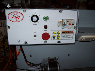
Some paint, and then a handmade label, assorted holes, controls and an indicator lamp and this is how the control panel turned out...

Figure 8 - Finished control panel

The label was made using techniques attributed to Peter Homann  along with a myriad of minor tricks I picked up over the years. The warning labels cover the real risks of the lathe cabinet, and operating the lathe including: electrical, rotating parts, read instructions, wear PPE (Personal Protective Equipment.. eg safety glasses) and the most important of all... I copied and modified the logo from Hack-a-day with the advice to "not let warnings put you off being creative, or learning" since I believe too many in today's society become too scared of warnings to actually try something new.

What else about the control box? There is an aluminium gland plate in the bottom face of the box for the passage of  cabling to the motor and to the E-stop at the tail-stock.

The entire cabinet was painted with "Bender grey" paint - the darker of the two colours used to paint up Bender. The colour is nice, and I have over 5L ( about 6 pints) of paint left from painting Bender so I'll be painting a few things with it over the next few years.

The only topics left to describe with this project is the electrical systems including:
Schematics, wiring, switch construction, and controls. I daresay those topics will be covered in about 2 more articles, and then that will be it for the lathe cabinet unless there are questions.

Sunday, April 10, 2011

Taig lathe cabinet - drip trays and panel beating

This article covers the construction of the drip tray (first and second attempt) and touches on the panel beating methods I used

As mentioned in the article regarding the frame, the objective of the lathe base was to have a substantial piece of metal which was thick enough to support drilled and tapped holes, magnetic (for use of mag-based tool stands), and to help dampen noise. Thinking I could do this by building a drip tray out of 4mm steel, I made a tray by scoring and cutting the sheet, and then bending and welding it up.


Figure 1 - pieces of 4mm sheet scored and bent


Figure 2 - 4mm sheet welded up to form drip-tray #1


Figure 3 - resulting drip tray from 4mm sheet - distorted and not flat

BIG PROBLEM - the resulting tray buckled during welding and would not provide a flat base. no amount of cussin' or hammering would fix that. - on to Plan B.

Plan B was to use a thinner metal to make the drip tray, and then use a separate sheet to form the solid base floor. The frame was built to support this design, and the base sheet cut and fitted. From that sheet, all other measurements for the drip tray were derived.

The drip tray is made from colourbond "sign-white" - a thin sheet metal coated to prevent rust (some kind of zinc-aluminium coating) and coated in a bonded white paint - it's used by sign writers to make shop signs - hence the name. The other side is a pale grey colour, and this became the visible side since it was easier than trying to remove the old vinyl lettering from the white side.

My source of sign-white is a number of discarded signs which I obtained soon after moving to this town. The frames for the signs quickly became stock for building a myriad of doors, shelves, etc, and the panels have become door skins, guards, and a number of other tasks. This lathe drip tray commenced the use of the last full sheet.


Figure 4 - commencing the folding of the drip tray (#2) - forming the wired edge

Since I don't have a pan or finger brake (yet another project yet to start) , I improvised using tube and angle iron clamped together (often the tube was one side of an old table frame). The "mallet" was a piece of pine timber, and a piece of 2"x 1/4" flat bar was used as a flatter to help crisp up the edges. I formed up a wire edge for the edges of the tray where hands would touch by folding the sheetmetal around a strip of 3mm x 25mm (1/8" x 1") strip and hammering it flat with a mini sledge hammer.. after everything was folded up, this gap was then closed up to complete the wired edge.


Figure 5 - completed drip tray with wired edges for safety

This method of folding was used throughout this entire project - drip tray, drawers, trays, control cabinet - all fashioned with bits of tube or angle iron, 3 clamps, a piece of timber (with or without a flatter), and a pair of ear muffs to drown out the noise.


Figure 6 - completed drip tray and back board


Figure 7 - Rear view of back board showing overlap

Next article will cover the swarf gate and accompanying swarf drawer.
Still to come:
Drawers, electrical circuit, "home made" switches, control panel

Friday, April 8, 2011

Taig Lathe cabinet - base frame

The frame of the lathe stand

The frame was built based a size calculated to permit the Taig lathe to be mounted with enough room to allow the mounting of a motor, space for changewheels, backgearing, control space for the leadscrew control, and any accessories I planned including a taper turning attachment and profile copier.
 

Figure 1- Base frame with headstock reinforcing

The overall baseplate dimensions became 500 x 850mm (20 x 33.5"). The baseplate became the core of the design with a sheetmetal tray built to sit under it with a lip coming up from the front and sides, and an extended lip coming up at the back making a swarf tray capable of containing swarf or coolant.


Figure 2 - Base frame with drip tray and top sheet

The frame was welded up from 20x20mm (3/4 x 3/4") angle iron, or tubing from the scrap pile.


Figure 3 - Base frame with backboard frame attached

The Taig lathe is a cantilever bed lathe with a foot under the headstock. To provide a strong stable mount for the lathe I welded a piece of 4mm (5/32") into the base. (shown in Figure 4) This means the lathe is mounted to 8mm (4+4mm) of steel, whereas the rest of base will have a thickness of only 4mm. I deemed 4mm as thick enough for magnetic bases, or drilling and tapping into, whereas I felt it prudent to have it thicker under the lathe foot, and for mounting the motor assembly.


Figure 4 -Base frame from rear, showing angle iron brackets for back board, and reinforcing sheet at headstock

The backboard for the lathe stand adds 560mm (22") to the height of the stand and runs the full width of 910mm (36"). The backboard is attached to the baseframe by some bolts mating the board to some angle iron brackets.(refer Figure 4)

The frame contains room underneath the baseplate assembly for drawers - the height of which is 100mm (4"). The drawer widths are governed by the spacing of the stiffeners added to support the plate under the lathe foot, and a small offset at the tailstock end to support the E-stop. The space behind the E-stop is used to house a "swarf drawer".


Figure 5 - Bare frame with drip tray and top sheet removed, backboard frame attached.


The frame has 2 fold-away handles attached for moving the lathe - these are located at each end of the base.


Figure 6 - The fold away handle at the tailstock end of the base frame

The backboard was clad with a sheet of polycarbonate approximately 6mm (1/4") thick (a salvaged shop display shelf when the local postoffice was renovated), and a piece of colourbond "signwhite" from a salvaged shop sign. The sheet of polycarbonate served 2 purposes:
a - the additional thickness stood the sheet of colourbond away from the frame at the bottom edge permitting the lip of the base drip tray to slide behind it - preserving the sealing of the tray assembly, and
b - the additional thickness added stiffness and "meat" to the backboard providing substance for screws to engage with, and to dampen any movement in the colourbond sheet.


Figure 7 - clad backboard - rear view.

A few other features are in the frame, but those will be elaborated upon during the articles describing what they support.
Overall dimensions - 710 (H) x 550 (D) x 910 (W)  = 28" x 22" x 36"

Sunday, March 13, 2011

Taig Lathe Cabinet - Motor Mount and unloader

I'll start documenting the build of the lathe cabinet using those photos still on the card in the camera (the other photos will have to wait until after the PC is rebuilt)

The Motor Mount
The original lathe stand used a jackshaft mounted on a wooden slide-way for a clutch, and speed control was limited to the cone pulleys on the motor/jackshaft - and then the standard Taig 6 speed cone pulley.

The new motor system would have the motor speed controlled by a VSD (Variable speed drive) giving infinite speed control over the range of 0-100%.
I still wanted a clutch (unloader) so I looked at various designs used by others and cobbled up a version of my own.

The belt tension aspect of the motor mount is loosely based on a design shown on Nick Carter's website. (www.cartertools.com)
His design uses rods for alignment, and a threaded rod for adjusting the position of the moving member. My design uses slots cut in the mount for alignment, and a threaded rod for adjustment.
The basic structure is made of two pieces of 50x50x3mm angle iron (2" x2" x1/8") welded together to make a channel 100mm wide and 50mm deep (4"W x 2"D). the length of the pieces is approx 200mm (8")

I then cut 2 pieces of 50x50x3mm angle iron at around 300mm (12") long and cut slots about 12mm (1/2") from one edge. The slots were a clearance fit on standard 6mm bolts. (Slots were cut using drills to mark the ends, then 1mm cutting disc in between)

Corresponding holes were drilled in the piece made earlier in the description, and 20mm (3/4") bolts were tacked into place so the threads extended out through the slots.
End pieces were measured and made up to close out the end of the longer pieces, as much for stability, but also to support the threaded rod used for the adjustment.
The moving part is driven by a nut which was threaded in, and then tack welded to the underside of the moving part.Nuts spun on to the threaded rod, and welded in place became the thrust surfaces for the rod's action, and one nut was welded in place out the front of the unit for adjustment purposes.


Figure 1 - base of motor mount - sliding parts.

The pieces already described do not actually mount the motor, instead they provide a base which can be adjusted. The part which actually supports the motor is a hinged channel (cut from the side of some 100x100x3mm square tubing) so it actually 100mmwide, and 15mm deep.
A corresponding piece is fabricated from 4mm plate to sit atop the moving motor mount part made earlier, and to support the channel piece just described. The channel piece supports the motor by means of 2 slots cut in the channel at right angles to it's long axis - these permit adjustment of the motor position along it's shaft axis.

The channel is hinged onto the mount plate, and a cam is placed near the mount hinge to change the angle of the channel. The cam was built by cutting an approximate shape from 4mm sheet, then  tack-welding a 15mm wide strip of sheet around the cam surface for wear reduction. The cam has a position where the "lifting effect" is stopped - this is the position where the motor is tilted back away from the headstock of the lathe.


Figure 2 - the built up cam which tilts the motor mount channel.


So the overall structure is:
the motor tilts forward and backward within a range of motion governed by a cam (35mm = 1 1/2")
which sits atop a sliding mechanism which adjusts belt tension over a range of 75mm (3")
The motor can also move along it's shaft axis by 25mm (1") via the slots its mounted in.

The cam is operated by a wire lever about 250mm (10") long located well out of the way on the LHS of the cabinet.


Figure 3 - completed motor mount assembly

A standard steel ruler pinched under one of the slide nuts was used to test the range of the tilt mechanism


Figure 4 - Motor mount system in the unloaded (belt tension released) position.

The recorded range of motion was approximately 35mm (1 1/2") between unloaded (no tension) to the loaded (tensioned) position.


Figure 5 - Motor Mount in the loaded (tensioned) position.

Why have the facility to drop belt tension via the lever?
#1 - ability to leave the lathe when not in use with the belt un-tensioned to prolong belt life
#2 - easier changing of positions of the belt on the 6 speed pulleys
#3 - less chance of driving the motor when moving the spindle by hand (new motor is a PM DC motor which would act like a generator if I spin the chuck by hand)

So based on this design whenever I change the belt, I would place the belt on the appropriate pulley range and push the lever up into the "loaded" position.
I would then use a 17mm socket to adjust the threaded rod and move the sliding part so the belt tension was where I wanted it.
Then I would use the lever to reduce the loading, and adjust speed ranges accordingly.

In testing, I have found the flat section on the cam is sufficient - I can "feel" it click in through the handle, and the tension stays constant during use.


Next couple of posts:
I have photos of the frame construction, basic sheet metal work, and the construction of the control panel i can access. It doesn't cover much of the control electrical system, but does cover the fabrication of the switches, and the panel-work itself.

Monday, March 7, 2011

Taig lathe cabinet - completed

Today I took advantage of some time away from work during the public holiday to bolt the Taig lathe to the new stand.

Some history...

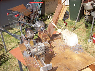
Figure 1 - original lathe stand

I bought the original Taig lathe from an amateur pyrotechnician in Brisbane in 2001 (or was it 2000?) The motor which came with it was a salvaged unit from a washing machine.


I modified the motor mount to retain the pillow block and 1/2" shaft, but mounted the motor and jackshaft on a set of sliding mounts which gave me a clutch in the form of a "belt unloader".


Figure 2 - motor mount and jackshaft on sliding mechanism

I put a drawer underneath the 18mm (3/4") MDF top sheet and used it this way ever since. In the meanwhile a removalist broke the jackshaft mounts, the motor board started a gradual twist (compensated for by inserting popsticks under the motor mounting), and the bearings in the motor started to fail.


Figure 3 - tail stock view of old stand

The motor controls (on-off switch) is mounted in the front of the white icecream container screwed to the baseboard - inside the icecream container is the start capacitor and the wiring out to the motor. - real high tech.

Over the past 5 years I commenced modifying the lathe by adding a leadscrew and halfnuts, converting the tool post and tail stock socket screws to thumb bolts, and building accessories.


Figure 4 - the conversion of socket screws to thumb bolts

So after essentially 10 years, this 12-14 year old lathe is getting a new cabinet and drive

That was the past - now here is the future...

Figure 5 - the new cabinet with Taig lathe in place


Electrical highlights
300W DC PM motor driven via a PWM VSD (Pulse Width Modulated) (Variable Speed Drive)
NVR and E-stop safety circuitry (No-Volts Relay)
4 switched GPOs onboard


Powered from a single 240VAC IEC power cord


Figure 6 - electrical cabinet

Mechanical features
Metal cabinet with enough "meat" to permit drilling and tapping accessories anywhere I want.
Swarf tray with gate in floor
magnetic metal base for DTI, etc
motor mount has a "belt unloader"
All painted up in "Bender gray" except the 4mm thick metal baseplate

The motor mount is loosely based on the Nick Carter design, but modified for my purposes with a cam operated unloader mechanism.


Figure 7 - the motor mount in the "unloaded" position

The control panel represented an interesting amount of work which will be covered in greater detail later. one of the fun parts was the logos and labelling - the frustrating parts was doing the wiring to a suitable standard which permitted easy construction, and repairs.


Figure 8 - close up of control panel

In all, about one month's work over weekends, and the odd day here and there (mornings during shift rostered days.) - estimated total labour time would  be 100 hours
The wiring took about 3 days since I had to redo some of it when my neighbour offered some advice on how to make it better for someone else to fault find in.
Everything except the motor and some electrical components was either constructed, or salvaged - the out of pocket expenses were around $200, and a large chunk of that was for the power supply.

I will do up some articles which highlight the construction process, with focus on the various components/ skills, but in the mean time I'm going to enjoy using this "reborn" lathe.