Showing posts with label indicator stand. Show all posts

Monday, March 7, 2011

Taig lathe cabinet - completed

Today I took advantage of some time away from work during the public holiday to bolt the Taig lathe to the new stand.

Some history...

Figure 1 - original lathe stand

I bought the original Taig lathe from an amateur pyrotechnician in Brisbane in 2001 (or was it 2000?) The motor which came with it was a salvaged unit from a washing machine.


I modified the motor mount to retain the pillow block and 1/2" shaft, but mounted the motor and jackshaft on a set of sliding mounts which gave me a clutch in the form of a "belt unloader".


Figure 2 - motor mount and jackshaft on sliding mechanism

I put a drawer underneath the 18mm (3/4") MDF top sheet and used it this way ever since. In the meanwhile a removalist broke the jackshaft mounts, the motor board started a gradual twist (compensated for by inserting popsticks under the motor mounting), and the bearings in the motor started to fail.


Figure 3 - tail stock view of old stand

The motor controls (on-off switch) is mounted in the front of the white icecream container screwed to the baseboard - inside the icecream container is the start capacitor and the wiring out to the motor. - real high tech.

Over the past 5 years I commenced modifying the lathe by adding a leadscrew and halfnuts, converting the tool post and tail stock socket screws to thumb bolts, and building accessories.


Figure 4 - the conversion of socket screws to thumb bolts

So after essentially 10 years, this 12-14 year old lathe is getting a new cabinet and drive

That was the past - now here is the future...
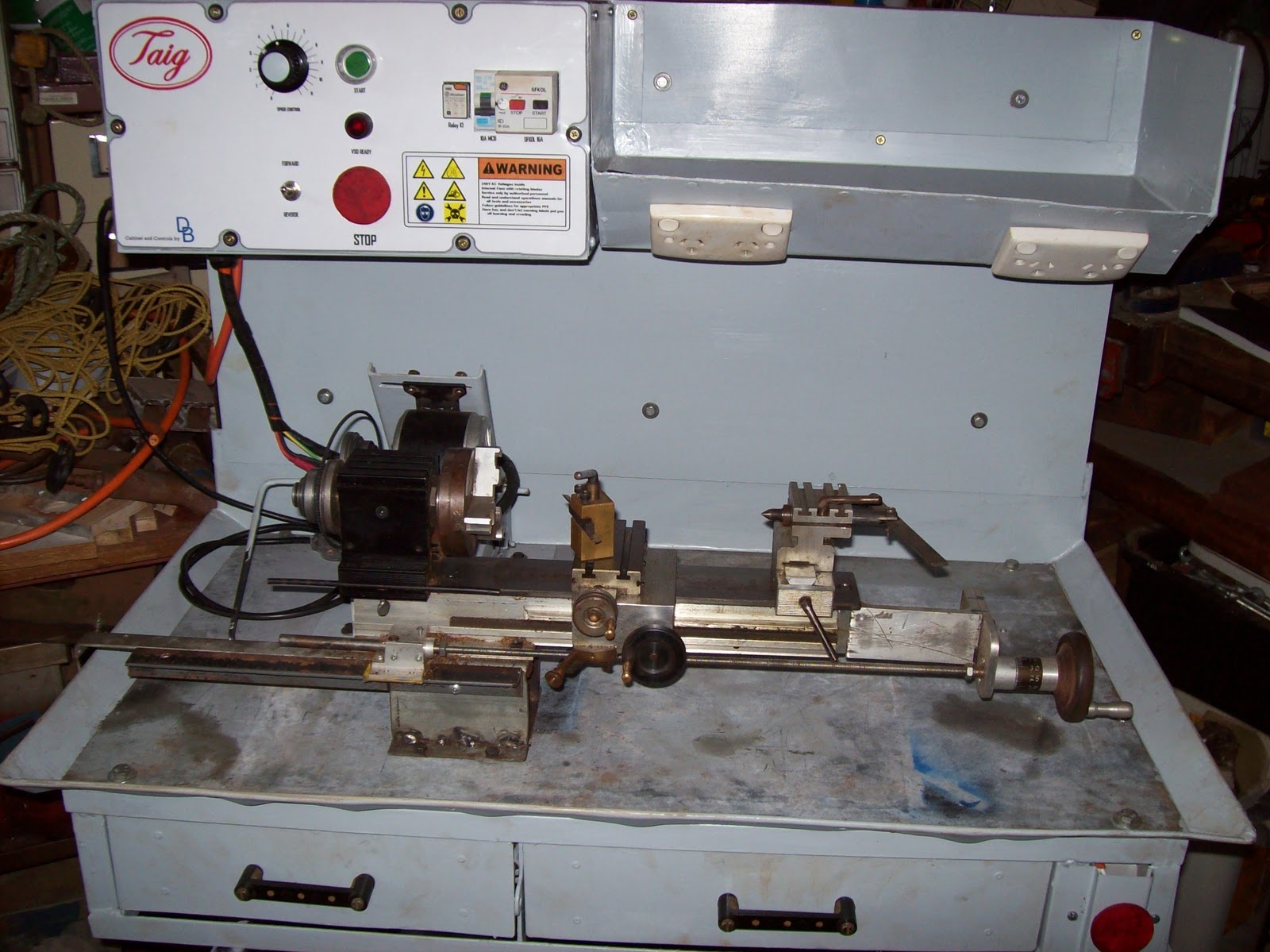
Figure 5 - the new cabinet with Taig lathe in place


Electrical highlights
300W DC PM motor driven via a PWM VSD (Pulse Width Modulated) (Variable Speed Drive)
NVR and E-stop safety circuitry (No-Volts Relay)
4 switched GPOs onboard


Powered from a single 240VAC IEC power cord


Figure 6 - electrical cabinet

Mechanical features
Metal cabinet with enough "meat" to permit drilling and tapping accessories anywhere I want.
Swarf tray with gate in floor
magnetic metal base for DTI, etc
motor mount has a "belt unloader"
All painted up in "Bender gray" except the 4mm thick metal baseplate

The motor mount is loosely based on the Nick Carter design, but modified for my purposes with a cam operated unloader mechanism.


Figure 7 - the motor mount in the "unloaded" position

The control panel represented an interesting amount of work which will be covered in greater detail later. one of the fun parts was the logos and labelling - the frustrating parts was doing the wiring to a suitable standard which permitted easy construction, and repairs.


Figure 8 - close up of control panel

In all, about one month's work over weekends, and the odd day here and there (mornings during shift rostered days.) - estimated total labour time would  be 100 hours
The wiring took about 3 days since I had to redo some of it when my neighbour offered some advice on how to make it better for someone else to fault find in.
Everything except the motor and some electrical components was either constructed, or salvaged - the out of pocket expenses were around $200, and a large chunk of that was for the power supply.

I will do up some articles which highlight the construction process, with focus on the various components/ skills, but in the mean time I'm going to enjoy using this "reborn" lathe.

Saturday, May 1, 2010

Indicator stand - magnetic - disassembly

I obtained a very damaged indicator stand (magnetic) which was to be thrown out. The damage includes the lack of the main post, all clamps, and the magnetic base is damaged by the loss of the front plate, switch lever, and some dings.
Below is a picture of what a complete stand should look like, with an indicator on it (picture taken from the Amazon listing for the Grizzly indicator/ stand set). I will rebuild the damaged one back to this level of usefulness, and use it with my existing indicator.


Before I can repair the damaged unit, I need to disassemble it, determine what needs fixing/repair, and then proceed from there. This page will cover the disassembly, another page will be written up to cover the rebuild once I've done it.

Since the front panel was already missing, I simply removed a brass lock screw from the side, and tried to remove the magnetic core from the internals of the base. I found the only way to achieve this was to tap the corner of the base on a block of wood, with the open end downwards, and use momentum of the core to pull it out (similar to a kinetic puller if you're into reloading) Once out, the pieces were laid out as shown below...


The pieces are: (from left to right) remains of actuating lever, magnetic core, spacer ring, base.

The base is a metal component, a singled piece, but it's made of four sections. All of these sections are visible in the photo below. The two sides (bulk of the base) are made of a cast iron, separated by a brass section about 5mm (3/16") thick. The final section is a zinc/epoxy shield which covers the hole at the back.

The brass separates the two iron halves, and effectively "breaks" the magnetic circuit between the two halves.

The magnetic core resides in the hole in the middle. The core comprises a strong magnet, with some pole pieces to direct the magnetic flux across the axis of the core. Some bonded plastic flanges are located at each end, and these plastic end pieces have a square hole molded in for turning the core.

The above photo shows the core with it's endpieces (the one on the right has a spacer ring fitted), whereas the photo below shows the square hole in the end for turning the core...


The spacer ring is to prevent the magnetic core actually contacting the interior of the base during normal operation. The diameter of the core is measured at 0.8mm less than the diameter of the hole it rotates in. The spacer ring is measured to centre the core in this hole, and this gives a rotating clearance of less than 0.5mm between the magnetic pole pieces, and the base.
The small gap is designed to offer minimal attenuation to the magnetic flux, but still permit rotation of the core. The base is designed (with the brass strip) to offer two flux paths from one side of the core to the other...
One path is through the iron side, through the magnetic material contacting the base, and then back through the other half - this path is the path which "grabs" whatever the base is sitting on.

The other path is where the flux flows within the same iron half - the flux path is vertical, and splits, with half of the flux circulating in the left hand iron side, the remaining flux in the right hand side.

That pretty much covers the internals of a magnetic base, and roughly how it works.
To repair this stand I'll be doing the following:

a - Machine a front spacer ring
b - Build a new actuating lever
c - Build a face plate to hold the lever
d - Build a post including mounting threads, washer, locknut, etc
e - Build the clamps, bars, etc to connect the indicator to the post.
f - Paint/ finish the components

As always I'll photograph as I go, and document after it's done with comments and findings.