The backboard contains two parts - interconnected but with separate purposes.
a - the control panel which contains all the electrical circuitry for controlling the lathe including protection, speed and direction control. The control panel also contains the breaker for the GPOs (General Purpose Outlets - aka "power points")
b - A tray for holding items used often, or needing to be up out of the way.

Figure 1 - Two parts of the top tray
The top tray was designed as a simple tray, with a false bottom which contained some GPOs. The front face of the tray was angled so the GPOs pointed downwards to prevent ingress of swarf, or coolant. I could have mounted them on the bottom face of the tray, but prefer the idea of being able to see the state of the switches at a glance.
The tray was simply folded up out of sign-white sheet metal in two pieces - the tray proper, and the supporting structure.
Holes were cut into the front face for the GPOs, and an access hole was cut in the LHS wall for cable entry.
The two halves were then riveted together, and sealed with silicone sealant to prevent anything from the top tray leaking into the false floor.

Figure 2 - Top tray assembled

Figure 3 - Top tray bolted to backboard - view from RHS.
The control panel section is a simple box. The top, rear and bottom faces are all folded from the same piece of metal forming a "U" shape. Flangles are folded inwards to form faces for the ends and front to be screwed on.
Each end piece is a separate sheet with the LHS containing a cutout to match the cable entry hole in the tray. The RHS sheet has a variety of holes cut in it for ventilation and power entry. Both side sheets have a bent section to form the side flanges for securing the front sheet.
Heavier gauge sheet metal was used for the side and front sheets to provide strength to the structure, and to support the control switches.

Figure 4 - front view of control panel showing internal flanges
I determined the size of the control box by lumping all the planned components into a pile, and then estimating it's volume. A considerable factor for cooling, wiring, and access was then added and the resulting dimensions then used.
Once built, the components were thrown into the box to test the layout and volume.

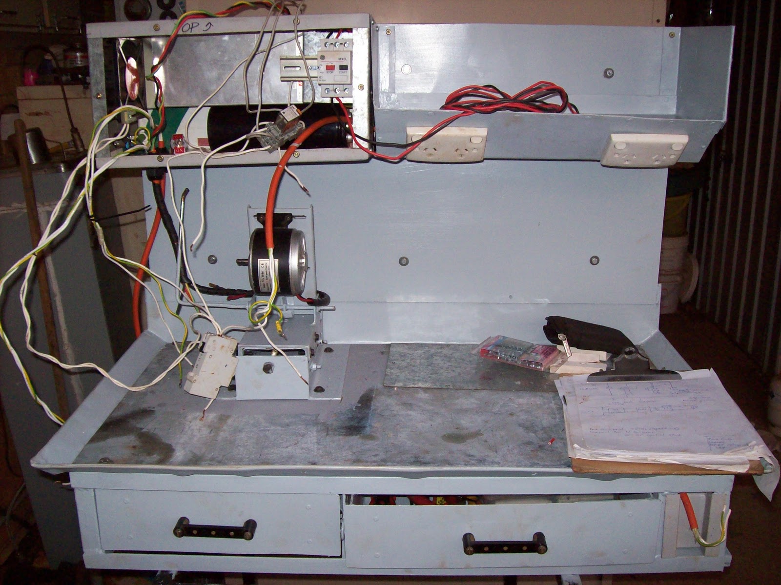
Figure 5 - Volume test of finished control box
A drawing of the box and it's airflow is shown below. The issue of the heat the 500W PSU generated was a concern, so I tried to design effective airflow into the cabinet. The PSU has a small fan inside it, and it blows hot air out one end... to make this more efficient, I folded up a small shroud to extend the fan end of the PSU to the LHS side wall of the control box, and cut a matching hole in the sidewall. A larger fan (surplus from when I upgraded my welder) was installed in the same sidewall - so cold air is sucked in, circulated through the control box and expelled through the PSU.

Figure 6 - sketch of air-flow and major components in control box
The front panel of the control box has been bolted on for the next photo. The front face is a simple sheet of galvanised sheet-metal.

Figure 7 - Plain front face of control box
Some paint, and then a handmade label, assorted holes, controls and an indicator lamp and this is how the control panel turned out...

Figure 8 - Finished control panel
The label was made using techniques attributed to Peter Homann along with a myriad of minor tricks I picked up over the years. The warning labels cover the real risks of the lathe cabinet, and operating the lathe including: electrical, rotating parts, read instructions, wear PPE (Personal Protective Equipment.. eg safety glasses) and the most important of all... I copied and modified the logo from Hack-a-day with the advice to "not let warnings put you off being creative, or learning" since I believe too many in today's society become too scared of warnings to actually try something new.
What else about the control box? There is an aluminium gland plate in the bottom face of the box for the passage of cabling to the motor and to the E-stop at the tail-stock.
The entire cabinet was painted with "Bender grey" paint - the darker of the two colours used to paint up Bender. The colour is nice, and I have over 5L ( about 6 pints) of paint left from painting Bender so I'll be painting a few things with it over the next few years.
The only topics left to describe with this project is the electrical systems including:
Schematics, wiring, switch construction, and controls. I daresay those topics will be covered in about 2 more articles, and then that will be it for the lathe cabinet unless there are questions.