Showing posts with label sheet metal. Show all posts

Thursday, June 16, 2011

Field desk - part 4 - Tray and lighting (additional information)

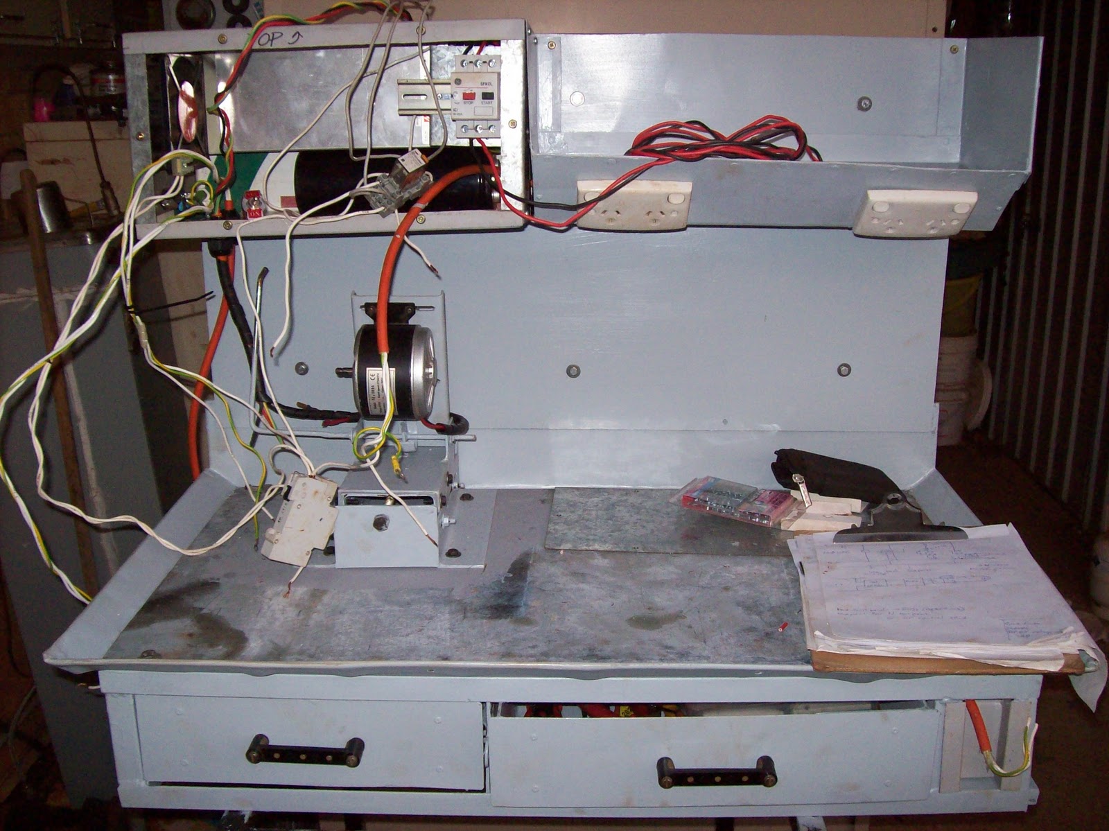
A little more information on the lighting, and a quick article concerning the tray for the top shelf.

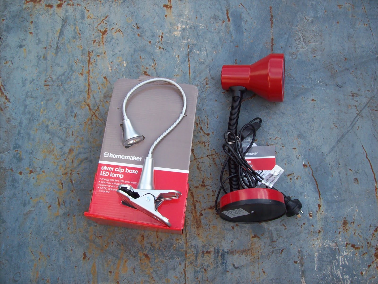
About 5 minutes after finishing part 3 of this series, I was filing the folder for that article when I found the additional photos I took as part of the lighting design...
Figure 1 - Lamps tested for use in the desk - LED lamp on left, incandescent on right
Photos of the two lights I trialed, including the LED lamp I used in this project, and a photo of the desk with a piece of DIN rail used to measure length and placement of the lamp.
Figure 2 - Trial of lamp placement using DIN rail

Paper Tray - Top Drawer
The other photos in this article cover the construction of a "paper tray" which is designed to fill the top shelf of the field desk. I plan on keeping an A4 notebook, CDR (with manuals), a couple of pens, etc in that shelf. The easiest way to achieve this is to have a drawer.
Figure 3 - Sheet metal cut out, prior to folding
The paper tray is simply folded up from sheet metal (more of my salvaged colourbond "signwhite") to make a simple tray, with a folded top edge on three sides, and one extended edge on the front. This extended edge forms a handle which allows the drawer to be pulled out from the shelf.
Figure 4  - Drawer in place on shelf
Since I haven't had the time to build a finger brake yet (still on the ever growing "things to do" list), I did all folds using the clamp over bar, wood and hammer method. One thing I found during that exercise was that you shouldn't hammer anything whilst you have a cold - all it does is screw up your inner ear whilst your sinuses are stuffed - Not a nice sensation.
Figure 5 - drawer painted
Once folded up, a couple of pop rivets to hold it all together and then it's painted up in "Bender Grey". In fact the entire exterior of the desk will be painted "Bender Grey" and will carry a suitable theme in the trimmings.
Figure 6 - Finished drawer showing folded handle on LHS
The painting and trim of the field desk itself will be the next article, then all that's left is a brief discussion about contents and that project is complete.

Sunday, April 10, 2011

Taig lathe cabinet - drip trays and panel beating

This article covers the construction of the drip tray (first and second attempt) and touches on the panel beating methods I used

As mentioned in the article regarding the frame, the objective of the lathe base was to have a substantial piece of metal which was thick enough to support drilled and tapped holes, magnetic (for use of mag-based tool stands), and to help dampen noise. Thinking I could do this by building a drip tray out of 4mm steel, I made a tray by scoring and cutting the sheet, and then bending and welding it up.


Figure 1 - pieces of 4mm sheet scored and bent


Figure 2 - 4mm sheet welded up to form drip-tray #1


Figure 3 - resulting drip tray from 4mm sheet - distorted and not flat

BIG PROBLEM - the resulting tray buckled during welding and would not provide a flat base. no amount of cussin' or hammering would fix that. - on to Plan B.

Plan B was to use a thinner metal to make the drip tray, and then use a separate sheet to form the solid base floor. The frame was built to support this design, and the base sheet cut and fitted. From that sheet, all other measurements for the drip tray were derived.

The drip tray is made from colourbond "sign-white" - a thin sheet metal coated to prevent rust (some kind of zinc-aluminium coating) and coated in a bonded white paint - it's used by sign writers to make shop signs - hence the name. The other side is a pale grey colour, and this became the visible side since it was easier than trying to remove the old vinyl lettering from the white side.

My source of sign-white is a number of discarded signs which I obtained soon after moving to this town. The frames for the signs quickly became stock for building a myriad of doors, shelves, etc, and the panels have become door skins, guards, and a number of other tasks. This lathe drip tray commenced the use of the last full sheet.


Figure 4 - commencing the folding of the drip tray (#2) - forming the wired edge

Since I don't have a pan or finger brake (yet another project yet to start) , I improvised using tube and angle iron clamped together (often the tube was one side of an old table frame). The "mallet" was a piece of pine timber, and a piece of 2"x 1/4" flat bar was used as a flatter to help crisp up the edges. I formed up a wire edge for the edges of the tray where hands would touch by folding the sheetmetal around a strip of 3mm x 25mm (1/8" x 1") strip and hammering it flat with a mini sledge hammer.. after everything was folded up, this gap was then closed up to complete the wired edge.


Figure 5 - completed drip tray with wired edges for safety

This method of folding was used throughout this entire project - drip tray, drawers, trays, control cabinet - all fashioned with bits of tube or angle iron, 3 clamps, a piece of timber (with or without a flatter), and a pair of ear muffs to drown out the noise.


Figure 6 - completed drip tray and back board


Figure 7 - Rear view of back board showing overlap

Next article will cover the swarf gate and accompanying swarf drawer.
Still to come:
Drawers, electrical circuit, "home made" switches, control panel

Saturday, February 5, 2011

Taig Lathe Stand/Cabinet - introduction

The current project...
My Taig lathe has been residing on a sheet of 18mm MDF for the past 10 years. The sheet has a wooden drawer built in underneath it, and a clutch/ jackshaft system for speed control. I will put a photo up in this series of articles, but not yet, this post is more a "preview".

Basically the old base (lathe stand) works, but it has limitations and problems. Some of the problems are the result of a certain removalist, some the result of bad design on my part, and most are simply the result of cutting corners due to cost constraints. - whatever the reason, it's time to make things better.

I'll do up a series of articles covering the design and build (mechanical and electrical) later, but for now here's some progress photos and a brief note of some features...
Lathe stand/ cabinet features:
full length/width drip tray
2 lockable equipment drawers under the drip tray with full extension
removable swarf tray
swarf gate in drip tray for dumping swarf
removable back board
4 switched GPO's (power points) with MCB
adjustable motor mount with belt unloader (clutch)
fold in carry handles
magnetic base with enough thickness for tapping holes if needed.
enough room to permit/ support my planned projects (backgear, change-wheels, taper turning attachment, indicator bases)

Motor controls:
24VDC 500W PWM VSD with reversing switch
16-20A over current protection
NVR (No Volts Release) circuit with additional e-stop at tail stock end


Just  waiting on the postman to deliver a few parts and this job is finished. The VSD cabinet (LHS rectangular section) contains:
500W 24VDC PSU (courtesy surplus parts online)
6800uF capacitor from a Seimens VVVF (for smoothing)
125mm fan (with some trickery in the ducting) for forced cooling
PWM circuit (with heatsinking)
control switches (Start, Stop, Speed control, reversing switch)
IEC socket with filter

DIN mount rail containing -
16-20A SFKOL overload protection device
NHP Terasaki MCB for isolating all 240VAC circuits
Industry standard relay mount and relay for NVR circuit
The DIN mounted components are accessible through the front panel (for resetting, or fault finding)


Both drawers are accessed from the front, on ball bearing slides with full extension - no excuse to have things lost in the back of the drawer again.


The removable back board supports the electrical circuits, and a tray for storing things during work - a work light will be attached to this backboard as well.


The range of travel in the "unloader" mechanism is shown here (the distance between the shaft and the vertical steel ruler - about 35mm (1.5")). The adjustable motor mount is shown midway through it's 100mm (4") of travel.


A photo from the tailstock end of the cabinet showing the tray mounted on the backboard - the rectangular holes visible in the slanting face are for the GPOs. The tray has a false floor and is sealed so the GPOs and cabling are protected. The GPOs were mounted in this manner (downwards sloping face) to provide easy access, but also make it impossible for swarf or coolant to fall into the outlet holes.

The materials used is basically salvaged sheet metal - some 4mm gal sheet for the load bearing areas, and sign-white (colourbond) for the rest.
The frame is a hotch potch of 25x25x3 angle, and some 25x25x1.6 square tubing.
All sheet metal bending (that worked - see future postings) was done using metal clamping with judicious use of hammers, wood blocks, and muttered cussin'
Most of the electrical parts are salvaged, however the power supply, and PWM section are purchased/ built  - all other parts removed from salvaged equipment (even recycled some bus mounts from a switch board to make the drawer handles)

The techniques, design, and details will be covered once I get the main computer fixed (power outage cooked one of the bridges in the mobo - lost the O/S drive and a few other peripherals), and few other demands on me at this time

Next update will most likely be in two weeks time - the pictures are already taken, it's just time to type, format and upload.
Friday, April 9, 2010

Grabby & Squeezy - Hands part 2


This page covers the shrouds of the hands, and fixing the hands to Bender's arms.

The shrouds are simple conical transitions. From my interests in model rocketry, I had a tool called VCP (Visual Centre of Pressure) which contains a simple little utility for generating the development of a conical transition on paper. I used the package to develop the template for the hand shroud using the arm diameter at one end, the flared diameter at the other end, and the length of the transition being set to the height I choose (83mm to match the arm diameter, but then padded the number out to 95 so I had room to adjust things during construction).
The resulting VCP printout was then cutout, and traced onto the colourbond offcut shown above.
I added some extra depth at the narrow end of the conical section for retaining tabs, and proceeded to cut out the shape.

The first shroud has been cut out, and rolled, the second one hasn't been cut yet. Rolling the colourbond would have been easy if I had some sliprolls, but I don't. I simply clamped some pipe to the benchtop, and pulled the colourbond piece through and manually forced the curve into the metal. I repeated the bending a few times to tighten the curve, then clamped, drilled, and pop-riveted the shroud together.

This picture shows the tabs I cut for retaining the shroud. Knowing the shroud can't move towards Bender's fingers due to the conical shape, I wanted to retain the rear of the shroud by pinching it in the wrist joint. I know if I'd measured and marked everything to the highest degree of accuracy, it wouldn't be necessary, but knowing my welding, the slightest warp would have betrayed the joint, it was easier to make the shroud retained against the joint for a seamless fit.

The photo above shows one shroud fitted to one hand, the second (right) as the two pieces. A small slot was ground into the wrist plate to provide clearance for the pop rivet. All rivets were beaten down flush with the sheetmetal to reduce the protrusion, then later tidied up with bog.


The hand is attached to the arm via the captive retaining bolt in the wrist plate. Prior to welding the spacer pipe into the plates, the bolt head was modified so a screwdriver could be used through the access hole to turn the bolt. The one bolt holds the hand in place, and positioning of the hand is accomplished by loosening the bolt, rotating the hand to a suitable angle, then re-tightening the bolt.

When the bolt is tight, the shroud to wrist seam disappears. There is a small step in the diameters at the seam, but that will be disguised when the painting occurs.


Since I was out of "Ole Fortran" beer, I had to make do with one of the drinks favoured in this area. The Lemon-Lime SOLO is a nice drink, and I can see why the guys in the workshop prefer it on hot days (Isn't that everyday around here?) I know I got addicted to them after one shutdown, so now I try and limit myself to only one can per day.

So what haven't I covered yet? Still to come; antenna, head, eyes, and then painting.

Grabby & Squeezy - Hands part 1

Grabby and Squeezy - these are the names of Bender's hands.

Knowing how important Bender's hands are to him, I spent a lot of time trying to figure out the best way to build them.

I'd been collecting his fingers for ages - the fingers are discharged CO2 cylinders from life jackets. I tripped over some at work one day and recognised the shape. The guys on shift, and maintenance saved them for me and I ended up with enough to make 4 hands. I'm retaining the spare fingers in the hope of redesigning the hands in the future.

As with everything else in Bender, I started with scrap 4mm galv sheet. I marked out a number of disks, 2 to match the diameter of the arm pipe, 2 to match the inside diameter of the hand, and 2 to match the diameter of the flared hand. The largest plate (flared diameter) was then marked out with 3 radially spaced holes to match the diameter of the Co2 cylinders. (finger plate)
A central hole was also drilled in all plates for the retaining bolt.


The above photo shows the components which make up the hand. From left to right across the edge of the welding table the parts are; Arm plate with captive nut, wrist plate, captive retaining bolt, pipe spacer, finger plate, 3 fingers.
The retaining bolt has had the threads nearest the head undercut so the bolt can spin in the wrist plate and not fall out, or bind. The spacer pipe seperates the wrist and finger plates.
The pieces above the components on the table include the made up shroud, but that will be discussed more in the next page (part 2).


The components assembled. The arm plate has been welded to the end of the arm, the wrist and finger plates welded to the spacer pipe with the retaining bolt already captive in the wrist plate prior to welding. The fingers were set through the holes, with a moderate degree of flaring, and then welded in place. Another view of the the assembled hand structure is shown below...

Part 2 of "Grabby and Squeezy" will cover the construction and fitting of the shroud, and placing the hands on the arms.