Showing posts with label salvage. Show all posts

Saturday, May 14, 2011

Dividing Head for Taig (and others) - Part 4 - sector arms, plunger, etc

Last article for the Dividing head.... What's left to discuss?
Sector arms
Plunger arm
Retaining Knob and spacers


Sector arms
The sector arms are patterned on the arm design from Tony Jeffree's website. The arms were first patterned out in cardboard, then cut out using a hacksaw, files, and drills.
Figure 1 - Sector arms with locking screw
The lower arm is then soft-soldered to a brass boss which protrudes to form a spigot for the upper arm. A screw has been drilled and threaded so it fully engages in the boss, but it's head overlaps the moving arm. A small brass cylinder was made to concentrate/ exaggerate the clamping force from the screw head.
In normal operation the screw is loosened by about 1 turn, and the upper arm can rotate freely on the spigot of the lower arm, once set at the appropriate arc angle (hole spacing), the screw is simply re-tightened to lock the arms in positions relative to each other. Both arms are still able to rotate as an assembly on the spigot of the plate carrier.
Figure 2 - Sector arms on plate retainer
A cover, which is actually a spacer, sits over the arm assembly in use, but serves no functional purpose other than to increase the distance between the arm, and the surface of the division plate.
Not long after starting to use this dividing head, I found the tips of the arms were difficult to operate if they crossed each other - kinda like trying to open scissors by using the tips... To alleviate that issue I turned the tip of the upper arm upwards to form a handle. I could have added a nice little knob, but I was worried about the extra weight on the slender arm.
Figure 3 - Spacer cover on sector arms

Plunger arm
The plunger arm - the arm which actually rotates the worm, is made of 1/4" thick brass strip. A slot (1/4" wide) was made through the middle by the use of chain drilling, and filing. This slot engages the flats filed on the worm shaft. A brass plunger mechanism was fabricated and the body soft-soldered to the arm.
The slot was made so the division plates could have multiple rows of holes, although typically I use only 3 rows of holes per plate at most.
Figure 4 - Plunger arm fitted to worm shaft

One problem I have with this plunger is that the threaded portion which holds the shaft and handle together will sometimes spin undone whilst using the knob for rotating the worm. I'll remember to dab a drop of superglue in there one day, but until then I remember to tighten the threaded joint before use.

Figure 5 - plunger arm secured by retaining knob
Retaining Knob and spacers
The retaining knob is simply a brass turned object, and my first attempt at knurling. The picture makes it look better than it actually is... the knob won't roll of the table because there is a flat spot on the bottom where the knurling "crunched up" - I can't explain why it happened, and I've since tried to rebuild the scissor knurler, but I keep having issues there.
Figure 6 - Retaining knob in profile
As mentioned with the sector arms, there is a cover which acts to space up the plunger arm. There is another spacer which sits above the arm to space the retaining knob. With both spacers in their correct locations, the arm is essentially clamped to the worm shaft not only by the slot, but also by the clamping of the spacers. It basically removes any clamping effects from the knob on the sector arms, since if I place the upper spacer in the wrong position (under the plunger arm) it will attempt to turn the sector arms when I operate the worm.
Figure 7 - Spacer ring above sector arm

Most of the brass was from the scrap merchant I mentioned in my previous articles, but the brass sheet for the sector arms was bought as scrap from the local radiator place (along with a clapped out 8" bench grinder which only needed $12 worth of bearings), and the brass for the plunger arm was purchased from the scrap bin of a local fabrication mob (NOT cheap)


 As previously mentioned, the spigot at the rear of the dividing head body permits the plate/worm assembly to rotated through about 180 degrees allowing the dividing head to be used vertically, or horizontally and still have the sector arms, division plate, plunger arm facing the operator.
Figure 8 - Plate assembly rotated 45 degrees to illustrate movement


That's about it for the Dividing head.. it's been used on and off over the years for a few jobs and will continue to be used for many more. The most recent job was making up a wrench called a "Torx-plus" so we could access the internals of a harddrive enclosure. The Torx-plus is a 5 lobed version of the more common 6 lobed "torx" bit. I made the bit  by drilling holes in the end of a piece of steel shaft to create 5 holes on the appropriate PCD, and then turned the holes away to only leave half the hole. The metal between each hole was used left in place to form the 5 lobes needed to turn the screws out of the enclosure.

I'll have to sit down one day and see if I can improve the design around the sector arms and plunger - it works, now, but it does need some improvement so the spacers aren't necessary - they are a pain if the top one gets put in out of sequence (below the plunger arm).

The field desk is progressing along, and will be the next article series at this stage. I've designed the locks and latch, and have commenced designing the hinges, support arms, lighting and handle. Somewhere in all that I'll need to decide what colour to paint it. This week I have jury duty, so it's possible I may get an hour each arfternoon/evening to work on the hardware.. here's hoping.

Thursday, May 12, 2011

Dividing Head for Taig (and others) - Part3 - division plate generation

The division plates used on this dividing head are made from old Hard Disk platters - the part of the harddrive which actually stores your data.
Each 3.5" hard disk will contain one or more of these disks which is 5.25" in diameter, with a 1" hole in the middle. The nominal thickness of the disks is around 1mm (less than 1/16") - I say nominal because I've found the more modern disks typically are thinner (less rotational inertia), whereas the older drives are thicker (up to 1/16")
The only thing you can rely on is that all disks in the same platter (collection of disks) will be the same thickness.


Figure 1 - Collection of platters destined to become division plates


I've been collecting hard disks for salvage for quite a while. The magnets are useful (see shed tip #1 ), and I also salvage bearings from them. The disks get shuffled into the pile for making division plates, and the casings go into the scrap aluminium bin (for foundry supplies) - only the boards, screws and little plastic doo-hickies get tossed. I learn a fair bit about mechanical design from looking inside the harddrive as well - there's some really clever braking mechanisms used to return the head, lock it, and so forth simply driven by ground effects from the spinning disk platter.

To make up a division plate:
I insert this mandrel into the back of the spindle of the dividing head. (see figure 2)

 Figure 2 - Direct indexing mandrel

The mandrel is made to expand and grip the inside of the spindle once the 1/4" nut is tightened up. A gear is placed between the 2 large washers which is an exact match (or multiple of) the desired index count. When I generated the 40 hole plate, I used a 40 tooth gear, but I could have used a 80 tooth gear if I had one.

 Figure 3 - Mandrel in place

The mandrel is sized to match the collection of C218 changewheels I purchased a few years ago. Those changewheels are the basis for the leadscrew of the Taig lathe and are the same metric mod 1, 20 degree PA changewheels used in the myriad of 7x12 lathes available in the US and other locations.

I place a chuck on the dividing head, and use a holder to grip the blank division plate in the chuck.
A centre drill is gripped in the lathe chuck using an arbor supporting a normal drill chuck.

Figure 4 - Dividing head spindle nose

A detent plunger mechanism is attached to the dividing head body which engages the gap between the teeth of the gear wheel. Turning and locking the spindle turns the blank plate, and all I need to do is feed the head into the drill to make the holes in the plate. The bracket supporting the detent plunger system is made from an offcut of an aluminium angle extrusion. The bracket is bolted to the body with two socket-head screws, and has holes to pass over the heads of the body bolts. Figure 5 (below) illustrates how it is fitted, with one securing bolt removed for demonstration purposes.

Figure 5 - Detent plunger system fitted

The detent plunger has a wedge shape when viewed from the side, but an inverted V shape when viewed from the front - this is to allow the indexing of the tooth tip instead of the gap between the teeth. This means I can index in the gaps of a 20 tooth gear, then rotate the plunger 90 degrees, and then index off the tooth tip and obtain another 20 positions - allowing me to generate a 40 hole plate from a 20 tooth gear.
The mount block for the detent plunger is bolted to the vertical arm of the bracket in one of 3 positions, allowing for a wide range of gear diameters. The large hole drilled through the body (from it's previous scrap origin) is used to secure the plunger with an elastic band if the internal spring is needing a little help.
The last article will cover (albeit briefly) the sector arms, plunger arm, and retaining mechanism.


Next project for documentation will be the field desk if I get it completed on schedule.

Sunday, May 1, 2011

DTI Mag-Base repairs

a while ago I discussed a broken mag-base I salvaged from being tossed out. That article discussed the dis-assembly of the mag base.

In an effort to get the "To Do List" a little smaller I finished off the repairs to the indicator base.
I used the spindle from a discarded tap to make up an actuating system for rotating the mag-core. I simply filed the required square shape into the section which used to hold the jump valve.
The threads which actuate the original tap were turned away, and replaced with a parallel section.


Figure 1 - Tap spindle filed to square

A plastic bush was turned to locate the mag-core inside the void in the mag-base, and to provide support to the spindle. The plastic was from a sheet of 25mm (1") thick plastic (nylon I suspect) that I rescued from a bin. A suitable square was cut from one corner, and a 10mm hole drilled through it. A 10mm bolt and nut were inserted, tightened up, and used as an arbor for the turning. Whatever the plastic was, it certainly was "stringy" in the swarf.


Figure 2 - Commencing turning the plastic bushing

A brass indicator/ handle was made from an old brass fitting, and some sheet brass, and soldered together.


Figure 3 - Actuating knob and pointer prior to soldering


The spindle was designed to pass through the front plate which was made from some brass strip. The front plate is shown on the RHS of the exploded view below (Figure 4)


Figure 4 - exploded view of mag-base

In the above exploded view, everything to the right of the magnetic core, and everything above the magnetic base were made from salvaged materials.

The magnetic core was filled back to remove the old damaged paint, and engraving markings. A few minor dings were cleaned up, and then the base was primed with cold-gal paint (Zinc-it) then followed up with a couple of light coats of Silver Hammer finish paint.

Upon assembly it was deemed too difficult to re-drill the existing holes to their proper spots, so new holes were drilled for securing the face plate.


Figure 5 - the magnetic core in the base with the spindle and bushing in place.


Figure 6 - The mag-base assembled

One of the salvaged lengths of steel from a gas strut was used to make the mast on this base - although a brass socket and washer was turned from an old extinguisher part (CO2 nozzle) to stiffen the joint instead of simply using the M8 thread.


Figure 7 - The  mast on the mag-base made from gas strut

An offcut of the gas strut remains, being about 125mm (5") long which will most likely be used for making one of the connecting rods.


Figure 8 - The completed mag-base next to the Taig lathe.

I've possibly made the mast too tall, but standing next to the Taig lathe, it has sufficient height to ensure access to anything I put in the lathe, or the vertical slide. I've yet to make the other smaller poles, joiners, and DTI connectors, but that should be fairly easy to do over the next few weeks.

That said, guess who's added more projects to the list... You'd think I'd have learnt by now, or maybe it's my curse (or is it blessing) to always have more jobs than hours to complete them...


I did up a quick explanation of how a mag-base works for someone, and decided to include it here in case anyone else needs to know how they work. I've since cleaned it up and converted it to a JPG.


Figure 9 - Theory of operation - magnetic stand

Sunday, August 22, 2010

Shed tips - free shim steel, and parallels

just another post to prove I'm alive, and trying to live up to my commitment to publish up the things I find useful, hoping someone else finds them useful.

Another "free" tip - shim steel
The anti-theft widgets I find inside PC software, DVDs and other packages often looks like a small rectangle. Inside is normally 3 pieces of incredibly thin steel - suitable for shimming tool bits up to 1/4" wide.
After several years of cutting these things open, only to fight with the sticky tape inside, this is the easiest way I've found to open the widget.

Figure 1 - the "unopened" widget

Using a sharp knife, slice the case near the bottom flange


Figure 2 - opening the widget

Remove the strips which you can easily - there may be one at the bottom under another layer of sticky tape - leave it at this stage


Figure 3 - the removed pieces, and one still in the case (under tape)

Cut the end off the rectangular plastic, as close to the end as possible

Figure 4 - sliced tape so the last piece can be retrieved

Insert the point of the blade between  the tape and the shim, and then slice back into the tape to cut the top off for at least 1/4".
Remove the remaining shim, discard the rubbish.

Result - Three pieces of shim, without any glue residue, or creases.

Bonus Tip  - "free" parallels
 an oldie but a goodie
Salvaged bearing races make good parallels, particularly for packing on the mill or lathe.
I took the time to dismantle a stash of saved bearings which were not worth saving (sand in the races)
Someone suggested drilling out the rivets holding the cage together - easier said than done, and it cost me a 4mm HSS drill - not again.


Figure 5 - old bearings too rough for use - destined to be dismantled

What I did was use on of my punches to drive the cage towards one side (punched in the gap between 2 balls) so the cage was deformed to the other side, then flipped the bearing and struck it back - I repeated this about 2 times and the cage broke at the point of the flexing. Using the point of the punch, I levered the cage material up, and then started winding it around the points of some pliers - most of the time the metal tore at the rivets, sometimes it broke, and all I'd do is commence from the other side and eventually all the cage was removed.
Then it was simply a case of pushing the balls all to one point in the races, and the inner race was able to be persuaded into the side without balls to drop away freely.


Figure 6 - a collection of free parallels for packing on the lathe.

Each bearing yielded 2 races with perfectly parallel sides, and a number of ball bearings which get filed away for use in detents, etc.

Speaking of detents - I pick up old disposable cigarette lighters whenever I'm out walking the dog - people are forever dropping them on the streets when they run out, or become damaged, The mainspring (the one pushing the flint up) is the perfect size for making/ replacing small detent springs (and extractor springs for rimfire bolts) - just another excuse to bring home junk, then pull it apart and file the parts.

What's on the horizon?
Webpage wise - I'll push to continue reviewing and recommending books - I can do that with little to no shed time.
Shed wise - Added 2 more projects to the "To Do" list (the "do to" list is at 12 major projects, and 23 minor projects and counting) - first is a couple of MOT spot welders (wound the first transformer last weekend), the second is building a electronics device to semi automate gear cutting... there are commercial offerings out there which do this, but the ulterior motive in this is getting my microprocessing skills back - I'm an Electrical/ Electronics engineer by training, but I spend more of my leisure time doing mechanical fitting - the irony has not escaped many people, especially myself.

Monday, August 9, 2010

Scrounging up materials - tips, etc

I am alive – I’ve just been burning the candle at each end, the middle, and a few other places.  Mostly work demands due to a sudden change in my shifts, but one thing upon another and I haven’t had as much time, or energy, to sit down and update this site.

I did get to do some cleaning in the shed on the weekend just gone, and as part of that I  photographed these two useful tips.

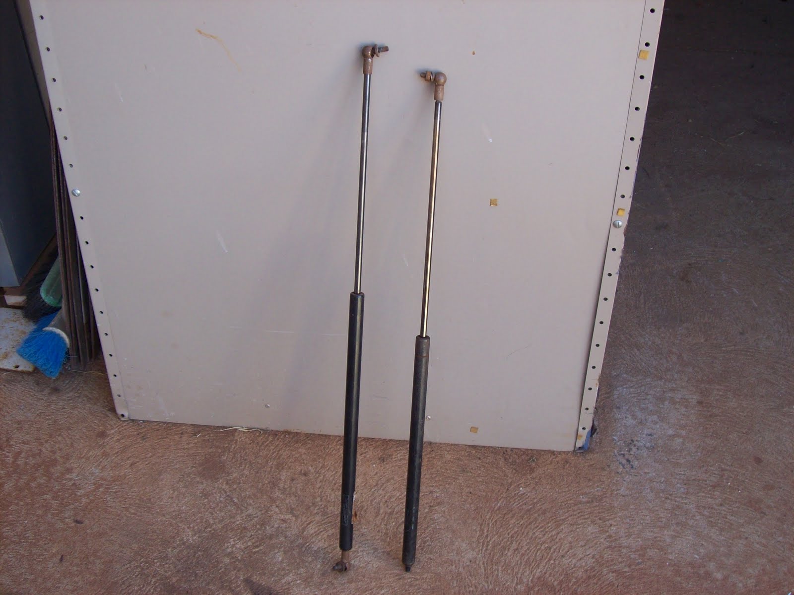
Firstly I need some STRONG steel rod for a couple of upcoming projects. One source of high tensile rod is the rod in a gas strut. I always keep my eyes open for any of these being tossed out, and I opened another 2 on the weekend in front of the camera. NOTE: opening these can be dangerous – I take precautions, but don’t blame me if you get hurt doing this!!!


Figure 1. Gas struts as recovered from being tossed out

The cylinder is filled with pressurized gas and oil. Near the end where the rod comes out there is some crimping which acts like a seal/ travel stop. I dress in appropriate PPE ("Personal Protective Equipment - in this case - ear-muffs, face-shield, leather apron) and work with the grinder and cut area pointed away from me. The first longitudinal cut in that area will suddenly release the gas and oil – I point that in a safe direction and let it vent out. Then once vented, I cut 3 or 4 longitudinal cuts for about 20-30mm above the crimped line. This allows me to remove the rod with it’s piston/ seals captive on the end.


Figure 2. Longitudinal cuts through crimped area to allow piston and seals to be pulled out of cylinder

I then grind off the peened over section of rod, and remove the piston/ seals from the rod.


Figure 3. Showing the peened end of the rod in the piston

The result is a strong, straight length of high tensile steel which has a polished surface. I now have 4 of these rods, one will be used to make the mast/pillar for the magnetic DTI base, another for my upcoming taper turner project, and the other 2 (matched pair) will be set aside as candidates for a Z axis slide in my CNC mill project. The photo below shows the 2 recovered rods on the RHS of the grinder.


Figure 4. Salvaged high tensile steel rods.


A useful tip I picked up from one of the contract firms I saw at a worksite…
We all have had a retractable steel tape measure break on us from time to time, I used to throw them out when I realized I “never get around to fixing them” – Not anymore.


Figure 5. Broken 8m tape measure


Instead I now open them up carefully

Using some heavy duty scissors (good tin-snips will do here as well) I carefully cut the measuring tape into useful pieces

Figure 6. Opened tape measure and snips

Since Oz is a metric country, most tape measures will have meters (with or with out imperial markings on the other side) so I cut the tape on the multiples of 1 meter.

Figure 7. Tape cut on meter markings

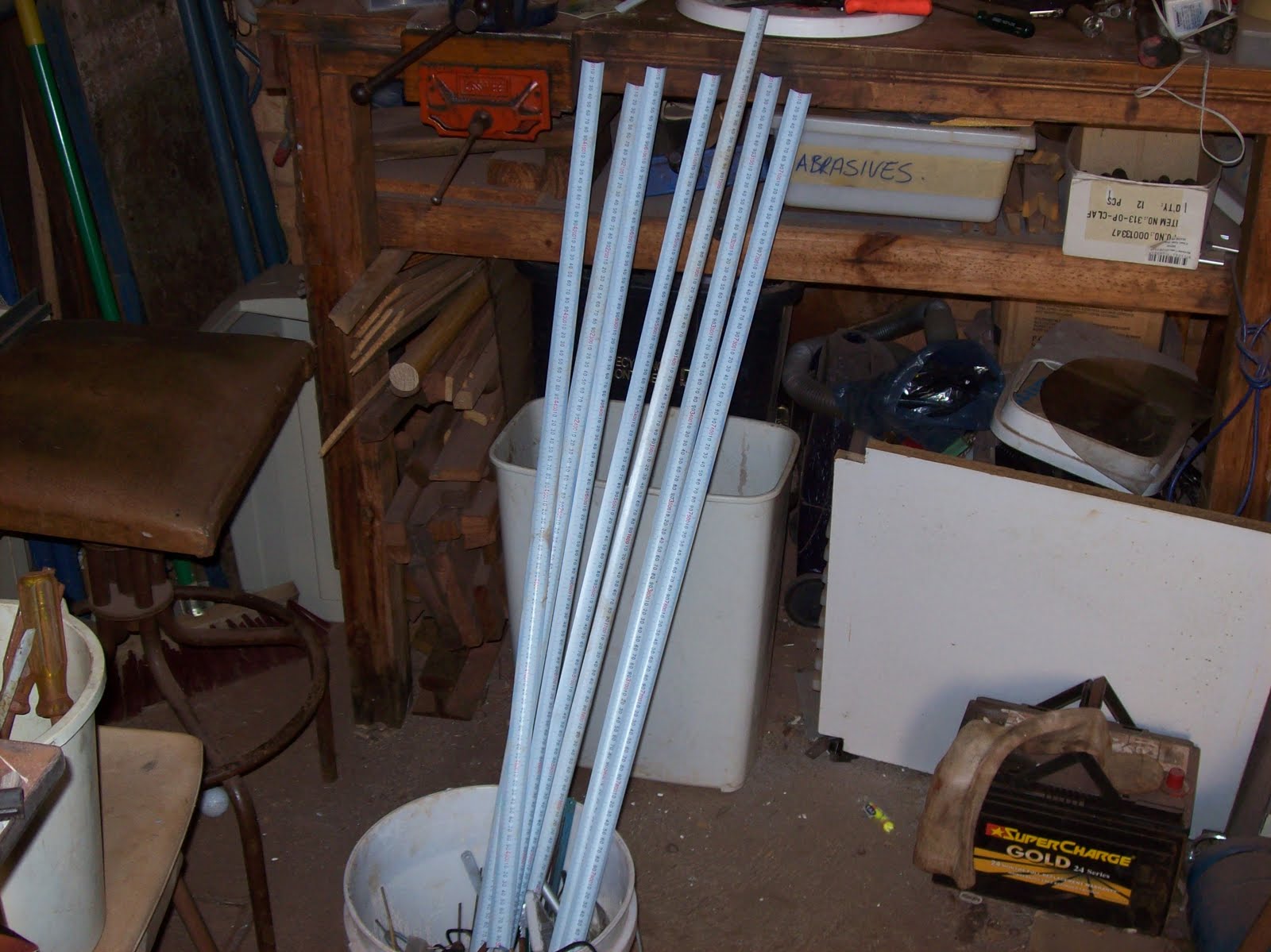
The resulting pieces are used as “disposable” yard sticks – useful for taking to messy places, using at the welding table, etc.

Figure 8. Seven 1m "yard sticks" made from one broken tape measure

I keep a stash of them threaded in the frame of the shed door – always there ready for use whenever I need a ruler for measuring something.


Figure 9. About 15 yard sticks threaded in the door frame of the shed.


I have 2 broken tape measures I haven’t cut up yet “in storage” for my CNC mill – these will be affixed on the sides of the axes for quick positioning/ verification under jog/ MPG control.

If I have time, I’ll put up the account of the other salvaged/ scrounged useful junk I worked on during this weekend’s clean up. (free shim steel and “free” parallels)

Time - it always comes back to that - a question of what to do with the limited amount you have each day...