Saturday, February 5, 2011

Taig Lathe Stand/Cabinet - introduction

The current project...
My Taig lathe has been residing on a sheet of 18mm MDF for the past 10 years. The sheet has a wooden drawer built in underneath it, and a clutch/ jackshaft system for speed control. I will put a photo up in this series of articles, but not yet, this post is more a "preview".

Basically the old base (lathe stand) works, but it has limitations and problems. Some of the problems are the result of a certain removalist, some the result of bad design on my part, and most are simply the result of cutting corners due to cost constraints. - whatever the reason, it's time to make things better.

I'll do up a series of articles covering the design and build (mechanical and electrical) later, but for now here's some progress photos and a brief note of some features...
Lathe stand/ cabinet features:
full length/width drip tray
2 lockable equipment drawers under the drip tray with full extension
removable swarf tray
swarf gate in drip tray for dumping swarf
removable back board
4 switched GPO's (power points) with MCB
adjustable motor mount with belt unloader (clutch)
fold in carry handles
magnetic base with enough thickness for tapping holes if needed.
enough room to permit/ support my planned projects (backgear, change-wheels, taper turning attachment, indicator bases)

Motor controls:
24VDC 500W PWM VSD with reversing switch
16-20A over current protection
NVR (No Volts Release) circuit with additional e-stop at tail stock end
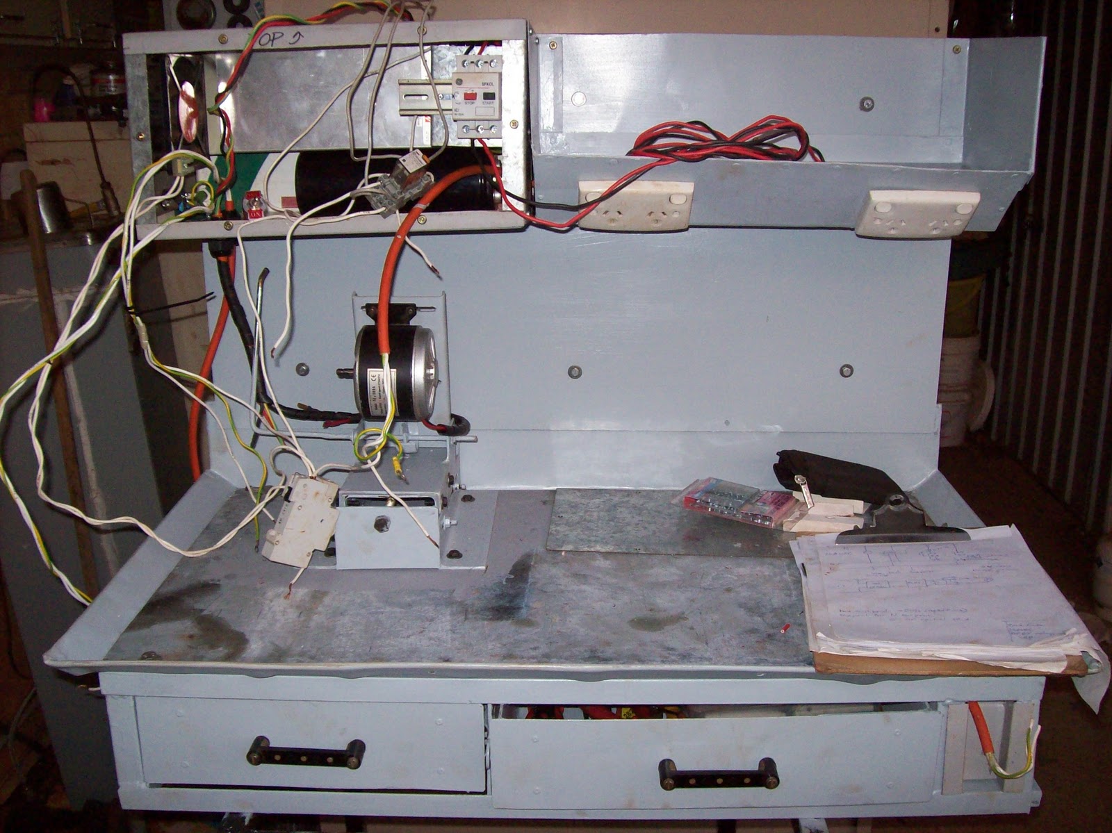


Just  waiting on the postman to deliver a few parts and this job is finished. The VSD cabinet (LHS rectangular section) contains:
500W 24VDC PSU (courtesy surplus parts online)
6800uF capacitor from a Seimens VVVF (for smoothing)
125mm fan (with some trickery in the ducting) for forced cooling
PWM circuit (with heatsinking)
control switches (Start, Stop, Speed control, reversing switch)
IEC socket with filter

DIN mount rail containing -
16-20A SFKOL overload protection device
NHP Terasaki MCB for isolating all 240VAC circuits
Industry standard relay mount and relay for NVR circuit
The DIN mounted components are accessible through the front panel (for resetting, or fault finding)


Both drawers are accessed from the front, on ball bearing slides with full extension - no excuse to have things lost in the back of the drawer again.


The removable back board supports the electrical circuits, and a tray for storing things during work - a work light will be attached to this backboard as well.


The range of travel in the "unloader" mechanism is shown here (the distance between the shaft and the vertical steel ruler - about 35mm (1.5")). The adjustable motor mount is shown midway through it's 100mm (4") of travel.


A photo from the tailstock end of the cabinet showing the tray mounted on the backboard - the rectangular holes visible in the slanting face are for the GPOs. The tray has a false floor and is sealed so the GPOs and cabling are protected. The GPOs were mounted in this manner (downwards sloping face) to provide easy access, but also make it impossible for swarf or coolant to fall into the outlet holes.

The materials used is basically salvaged sheet metal - some 4mm gal sheet for the load bearing areas, and sign-white (colourbond) for the rest.
The frame is a hotch potch of 25x25x3 angle, and some 25x25x1.6 square tubing.
All sheet metal bending (that worked - see future postings) was done using metal clamping with judicious use of hammers, wood blocks, and muttered cussin'
Most of the electrical parts are salvaged, however the power supply, and PWM section are purchased/ built  - all other parts removed from salvaged equipment (even recycled some bus mounts from a switch board to make the drawer handles)

The techniques, design, and details will be covered once I get the main computer fixed (power outage cooked one of the bridges in the mobo - lost the O/S drive and a few other peripherals), and few other demands on me at this time

Next update will most likely be in two weeks time - the pictures are already taken, it's just time to type, format and upload.

Saturday, January 15, 2011

shed PC cabinet, and electronics test gear

another set of projects!!! - Yes I know - got more than enough on my plate as it is, but it is related (see end of this post)

I needed a PC in the shed for programming work. Given the lack of space, the easiest thing to do was put the PC in a wheel-able cabinet, and packaged in such a way to permit it to be collapsed as small as possible.

I'd rescued an old 3M overhead projector a couple of years ago, and the wheeled stand it came on... This stand, with a few modifications, became the PC cabinet.

The original stand had a top which was set approx 6" (150mm) under the level of the top vertical posts, and the 2 flip out leaves attached to the posts. I raised the top shelf to line up with the posts, and then closed in the underside on 3 sides with some old sheet metal.  I took another piece of metal to work and bent it up to make a door for the fourth side.


The "front door" of the PC cabinet is the grey sheet of metal on the RHS of the picture - with black cloth tape covering the cut edges for hand protection.


The above photo shows the LHS leaf in the raised position - whereas the other photos in this article show both as lowered.

The PC is an antique (old celeron from memory) but it does what I need (runs the PICAXE suite of software). Network is accessible (if I run out the 15m patch lead) and the speakers, mouse and keyboard cabling is wrapped in a spiral wrap and pinned under the top shelf.

Currently (due to other projects) the most this PC does is play music for the shed area - the programming has been on hold for a few weeks now due to other commitments.


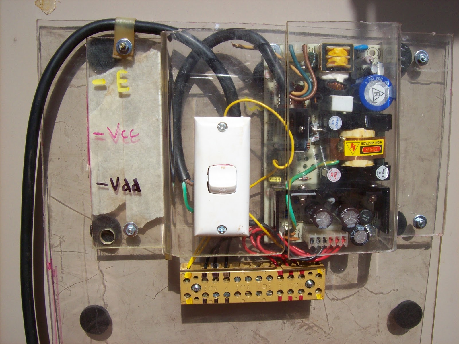
As part of the PICAXE work, I needed to rig up a 5VDC power supply for the breadboard and other circuit prototypes. Digging through my boxes of salvaged gear I found a near new 5VDC SMPSU. Using some scrap pexiglass, I fashioned up a board with the SMPSU encapsulated at the top. The scrap pexiglass had some bends in it already, and I used them to form the cover for the 240VAC section, and to mount the power switch.


It was a simple case of then bringing the 5VDC and COM rails out to the prototyping area by means of the terminal block. I also brought the mains Earth out as well. The colour code for the terminal positions is shown on the LHS of the cover.
LRF are applied on the bottom of the unit to stop the fixing screws from scratching up the top of the cabinet.


The unit fits nicely in the box with the other electronics bits.


Why PICAXE?
I needed something, and I was so out of date with my previous experience (6502, 8086, pic16f84) that I asked on the newsgroups what was the best to come back in with... the suggestions included Arduino and other systems, but PICAXE came through loud and clear as suited for what I'm trying to do...
I've a project to help someone who's eyesight is going. He's a machinist who's finding it hard to use a standard dividing head - I can't afford a "DivisionMaster" (excellent product designed by Tony Jeffree) so I'll try and build my own version (with several features not in the original - suited to the user's tasks) and bring my skills back up at the same time.
That is the story of my life so far - get an idea to do something, identify pre-requisite equipment and skills, acquire those, find there are more needed, etc ad nauseum.
Kinda the model engineer creed - "Build a jig to build a tool, to build a jig, to build a tool, to build a jig to build a project". In my case the lathe was bought to build a micro hybrid rocket motor, but the lathe needed parts so I started building parts, which meant I needed the furnace, which meant I needed to learn.... and on the story goes.
Don't take the above as a complaint - by the time I build that motor I'll have a fully equipped workshop, an amazing set of skills, and a very diverse set of experience - all I need is time... and patience... and space for junk... and money for bits...       :)

welding helmet renewal

I learned to weld (SMAW - aka Arc welding, aka "Stick welding") with a standard CIG "rockhide" full face helmet. You had to flip the helmet up and down to see whenever the arc wasn't running. Better than the handheld mask I used a few years later, but still painful to use compared to the newer "speed glass" style auto-tinting helmets. It's so much easier to weld when I can see the tip of the rod moving up to the point of the weld, instead of losing sight of it due to flipping the filter down

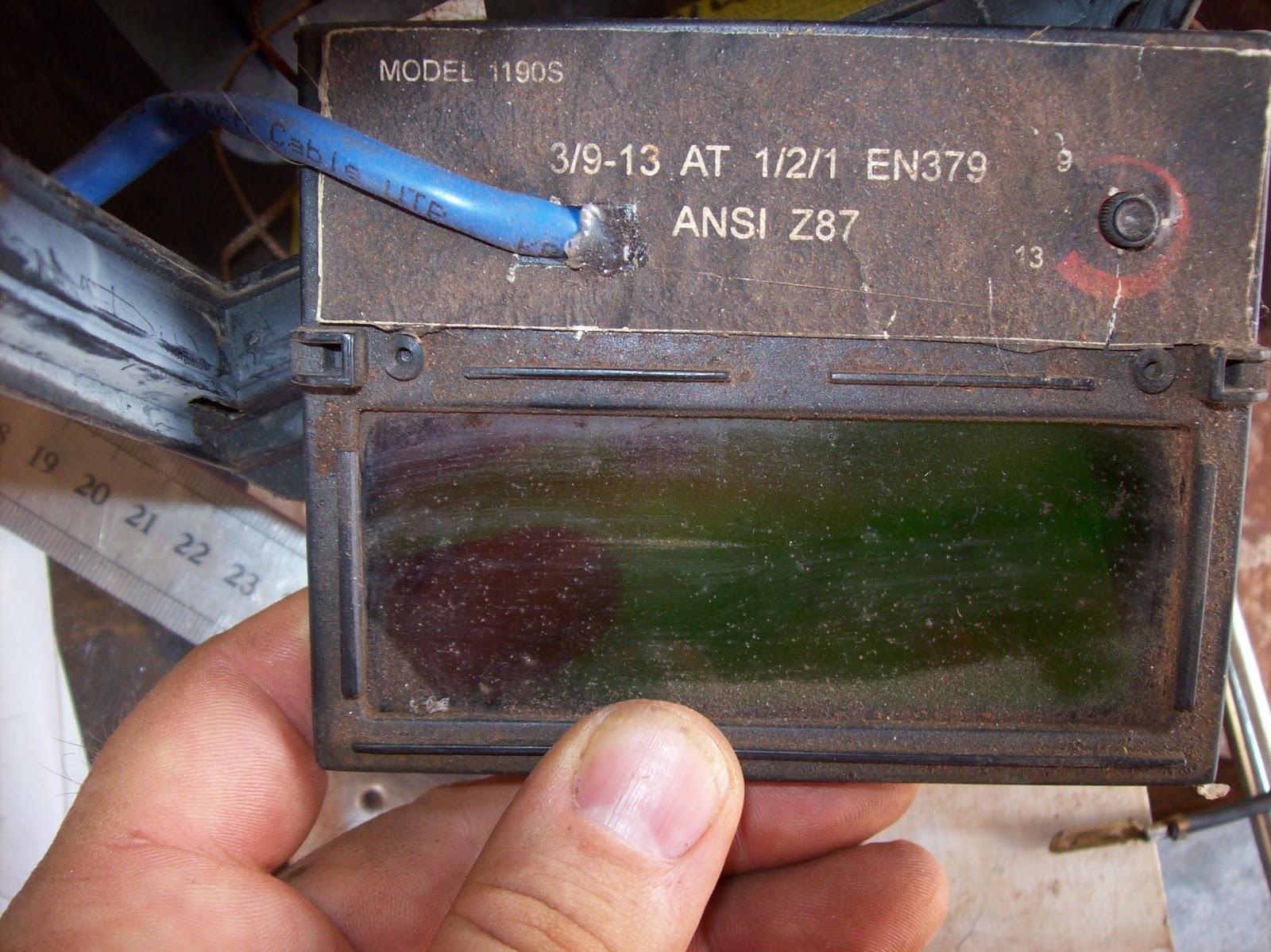
I bought a cheap helmet and used it for several years, and eventually it stopped working. Being the tinkerer that I am, I opened up the main unit and discovered a few things...

The helmet has a solar cell on it, and was advertised as never needing batteries since it charged from the sun. The batteries inside were 2 silver oxide non-chargeable button cells. My guess was that the solar cell reduced load on the batteries, but was never able to charge them. (Silver oxide batteries aren't rechargeable)

The other finding when I opened up the unit was that the nominal 6VDC across the 2 batteries was only 2.8VDC... I can hardly complain since they lasted seven years.


The rest of the circuitry is under the white "potting" used to protect the circuitry - I never disturbed that, just accessed the silver terminals which used to be spot welded to the original batteries.

Armed with that finding, I quickly fashioned up a 6VDC supply and connected it to the original battery leads (with the old battery removed) and tested the helmet - it worked.


The photo above shows the hole drilled through the back panel of the glass unit, and some flexible Cat5 cable led through for accessing the power terminals of the electronics.

A more permanent solution was made up...
The battery holders are from some cheap solar garden lights the dog broke
The cable is some flexible Cat5 patch cable
A number of holes were drilled in the helmet to affix the battery holders, and cabling.
All holes were then sealed over with some hot-melt glue, and painted over to block the UV from the welding operations.


Problems found with this solution:
Firstly the weight of 4 AA batteries sitting at my mouth level caused the front of the helmet to always hang down - rendering the friction locks at the headband useless - I ended up resorting to a short length of cord which runs from the top of the helmet to the back of the headband to stop that
The other issue I found was the attempt I made to have the power "switched", and removable - the 2 automotive crimps - frankly they proved more trouble than benefit. I'll cut them out and replace them with a soldered joint.


What else do I know about these units?
They don't like being dropped in quench buckets full of water
They don't like sweat dripping into them - day after stinking hot day
They can be replaced for around $30 via ebay (6shopriver is an example seller - no connection)

I don't consider the repairs I made to be a waste of time, they bought me some time so I could finish the job until I could replace the failing helmet. I will fully repair this helmet if possible and keep it as a back up.

shed tips - foaming tools, and disposable nozzles

Foaming tools

Basically a number of tools come in either blow-mold cases, or metal cases with blow-mold inserts. The decision to use blow-mold is based on providing a close fit to the tools in the case, without the cost of the old style wooden inserts.
There is a problem with the blow-mold inserts - breaking down due to age and vibration. the plastic liner breaks down and cracks apart due to the weight of the tools and eventually becomes useless.  Following the advice of those wiser people, I take the time to fill the backs of blow-mold liners so there isn't as much "give" in the liner, and the tools don't break it down as much (if at all)

The basic principle is to fill the voids in the back with something disposable and durable - currently I use expanding foam (the single expansion type, not the one which expands again when contacted by heat or water), but in the past I've used silastic (caulking sealer) bulked up with either sawdust, or scraps of foam, wood, or even general shed rubbish (broken hacksaw blades, etc)

Using foam
Access the underside of the blow-mold liner


fill the gaps with expanding foam


apply a sheet of heavy card (old filing cabinet suspension files) and weight it down until the foam cures


if you remove the card,you will find the foam pretty much filling all large gaps, but maybe missing some of the smaller ones - sometimes I refill them, other times simply leave them.


The photo below shows one weighted down liner, the other simply left uncovered and unweighted during the foam cure


As seen below, the unweighted one cured with large air bubbles under the foam, basically providing no support to the liner and the tools. The cut way pieces of cured foam aren't tossed away, instead they are pressed into the gaps, then refoamed and covered and weighted. As mentioned at the top of the article, the filling doesn't need to be anything flash, so offcuts of foam work fine.


I know people who use plaster for this some task - works well - my only concerns are the weight, and the holding of moisture inside the tool case.


Disposable nozzles for foam dispensing
The foam dispensing can nozzle - the sales guy from ramset told me that the expnding foam valve is a single function unit as mandated by the nannygovt  - as a result I buy my can (local trade store) and collect up a handful of straws from macdonalds. I cut the supplied nozzle tube at 1" (25mm)


and slide the macdonalds straw over the original (shortened) nozzle tube - this makes cleanup much easier (throw the straw away, and blow out the short piece) - As long as I schedule all my foaming for one day, I can usually use up the whole can before the internally sabotaged valve locks me out of the can.


Upcoming posts -
New life for an old welding helmet, and the lathe stand/cabinet

Friday, December 17, 2010

still alive -barely

this is more a message to say I'm still alive - apologetic for not updating this page recently. Kind of run ragged with work, community involvement, sorting out various issues (people, PCs, and other "interesting times")

I did get to use the Santa costume the other day, so already it's been used, and got good feedback.

Expecting updates/ progress over the next few months on the following projects:
MOT Spot welders
DTI stand repairs/ rebuild
Picaxe work
portable PC/electronics bench
I daresay there will be more (I've a "things to do" list of over 3 pages single spaced)...Updating this build log is part of it all.

Wednesday, November 3, 2010

Santa costume - hat and final - part 6

The last of the postings regarding making the Santa costume...
The Hat.. Unfortunately the shots I took during the sewing of the hats themselves did not come out (still figuring out why) I made two hats, one standard traditional hat which is basically a cone with a circumference of 650mm (26"), and a height of 600mm (24"). The second hat was a experimental model which will be described soon.
Each hat comprised of a velour outer, a red poly-cotton liner, and fur trim at the brim, and a fur trim pompom at the top.


Figure 1 - hats - Experimental, and Traditional

The liner was simply a truncated cone of similar dimensions to the traditional hat (circumference of 650mm, and a height cut down to 300mm. If worn by itself, it would resemble an oversized cap.

The outer was sewn along the edge (right sides facing, then turn inside out to conceal the stitching), and then the fur trim stitched to the outer so the stitching was facing inwards. The liner was then placed inside, pinned and stitched into place to cover the seams for the attachment of the fur trim at the brim.

The pompom at the apex of the cone was handstitched on.

The experimental hat (combination hat and scarf) was patterned on the traditional conical pattern, but then at the 350mm height, the cone was changed to it had a total height of 1800mm (72"). This meant that the hat resembled a long tube of approximately 100mm (4") diameter for most of it's length, with a flare at the end which took the diameter out to 200mm (8") for the last 350mm (14"). All other aspects of the hat (including the liner) were unaltered from the traditional pattern.


Figure 2 - Pompom making - material, and octagon

So the pompom would match the fur trim used elsewhere in the costume, I made the pompoms from the fur trim. A square of fabric was cut - approximately 150 x 150mm (6" x 6") and the corners folded inwards to form an octagon. A heavy thread was loosely stitched in at each corner, and then around again bisecting each  side making 16 points evenly spaced around the octagon. the thread was gently pulled up so the corners and sides pulled in, and the resulting hollow space was filled with assorted offcuts from the fur trim.


Figure 3 - Hollow created in pompom by pulling threads up

It was then pulled up tight and tied off resulting in a pompom which was about 65mm (2.5") in diameter. The heavy thread used to make the pompom and tie it off was left threaded to the hand needle during the previous steps, and then used to stitch the pompom to the hat's apex.


Figure 4- Pompom hand stitched to hat

Other accessories and costume tips.
 A couple of shots of the bag which attaches to the belt for holding keys, mobile phone, lollies (candy), etc. Simply a bag made of velour offcuts, and lined in poly cotton - simple belt loops on the back for attachment
Figure 5 shows the interior view of the pouch with a mobile phone, and some car keys in it for the test.


Figure 5- Pouch on belt - interior view


Figure 6 - Pouch on belt, exterior view

The wig/ beard I purchased off Ebay for the costume - 100% polyester, and quite good fit, and shape. It cost about $30 to buy including shipping.


Figure 7 - polyester wig and beard set.

And lastly, some white zinc sunscreen paint... I've played Santa before for various groups (Church, charities, clubs) and seen many others play the part.. I have fairly thick dark eyebrows which show through on most wigs. If I apply a smear of the white zinc to my eyebrows, they whiten out as if I've aged 50+ years, and they don't look out of place. - It beats my old trick of gluing threads from cotton balls to my eyebrows with PVA (White) glue.


Figure 8 - White zinc sunscreen paint (with other unused colours)


Unfortunately we were unable to find a local source of the white zinc paint without buying it in a triple pack with the other bright colours... they'll get fobbed off at some future date, since we're not big fans of running around with fluro blue, or pink faces.

Next project things to document... MOT spotwelder progress, reviewing books, and progress on other projects.

Monday, November 1, 2010

Santa costume - belt - part 5

Santa's belt

The idea was to use some near new automotive seatbelt material taken from one of the cars we'd cut up in training. Based on the that material, I designed a large brass buckle to suit.

Since I didn't have any suitable material to make the whole buckle from one piece, I decided to use some thin brass shim stock for the face of the buckle, and build the bulk of the buckle from thicker, but smaller brass material. Why couldn't I cast a buckle??? That's a story for another day....grumble and mutter.

I cut up the shim stock sheet to give me the shape I wanted, plus folding pieces to cover the joints.


Figure 1 - brass shim stock, and other material

I then cut up some 3/16 x 2" strip to give me the shapes I needed to fill in the back of the buckle. I then folded the shim stock up over the inserted pieces, and sweated it all together with soft solder. My torch is a Primus (Seivert) propane torch with a pencil tip.


Figure 2 - cutting the shim stock with a jeweller's saw


Figure 3- folding in the pieces prior to soldering


Once finished I tested the buckle only to find it didn't "grip" the material well enough to give me confidence. I considered adding a small barb in the buckle so it would grip, but figured it might pose a hazard. Determining the issue resulted from the excess clearance in the buckle openings, I drilled the buckle in four places and inserted some 1/16" stainless steel wire to close up the gaps. In fact it allowed me to double the material through the buckle, adding security and improving the appearance. The wire was cut from an antistatic dissipator from an old CO2 fire extinguisher


Figure 4- Buckle - Mk 1 - not suitable


Figure 5. Buckle Mk2 - with wires inserted


Figure 6. The good buckle threaded onto the belt material

I also made a smaller version of the buckle - reminiscent of a military buckle for capturing the excess belt length (tail as it were) - together they both hold the belt up nicely, and I need not fear the jacket coming open. (I started the smaller buckle while trying to think of a way to salvage the first buckle - thankfully I was blessed with some inspiration there... it would have been a shame to waste it.)


Figure 7. Both buckles on the raw material

Once it was all together, I noticed the seatbelt material would shine in certain light, and it looked distracting. To make the belt more consistent, I over-sewed it with 3 layers of black poly-cotton, and sewed rows of stitching the full length on 6mm (1/4") centres. This added a nice touch to the fabric, and allowed me to taper the open end of the belt making it easier to thread and prevent fraying.

Once the brass was polished up, the belt came out wonderful... the buckle adds a bit of weight, in fact the entire belt weighs in at around 1kg (~ 2 lbs)

Next installment - the hats.