Showing posts with label Bender. Show all posts

Friday, April 23, 2010

Hose suspenders - Part 1

OK, I'll openly admit it, I'm not a tradesman... I'm a dabbler. If you haven't already noticed it, some of what I show in these pages are mistakes, errors, and substandard welding. It's not from a lack of wanting, just a lack of training. Half of what I put these pages up is to show what can be done, the other half is to show what shouldn't...
I was once told that a Wise man learns from the mistakes of others - learn from mine. (you won't have time to do them all yourself!!!)

I offered to make some "hose suspenders". These are used by firemen for securing hoses running up ladders during structural fires. The suspender comprises two main parts, the first being made of steel, and resembling a large fish-hook. A sketch of it is shown on the welding table below....
The one I saw (to take dimensions from) had been forged from 3/8' (10mm) rod, but since I haven't built my forge yet, I figured I'd built these from welded pieces of steel. The ring at the bottom would be made from small pieces of pipe, and the two "hooks" would be made from 3/8" rod.

I obtained some 3/8" rod from the workshop, but all that was available was square rod, not round. I decided to make the "round hook" first by bending the rod around one of the pipe offcuts left over from Bender's legs. I welded the offcut to a scrap of steel as a jig.

The above photo shows the steel in the jig (Mk1) - all chalked up for the photo, and the arrow pointing the direction of the bend.

Cold bending 3/8" square rod was fairly easy, but getting it to conform to that curve was not easy. Sure I could have threatened it with the hammer, or swore at it, but I needed a better plan.

Mk2 jig basically added a "slipper" to the bend - a 1/2" (13mm) rod was welded in the centre of the pipe via a hole and plug weld, and a pipe handle was made to hold a slipper against the rod being bent. The slipper was nothing special, just a 1" (25mm) piece of pipe dropped over a 1/2" (13mm) rod.

The slipper keeps the 3/8" rod against the former in the jig through the entire rotation of the slipper pipe. This forces the rod to bend just as tightly all the way around the 180 degree turn.
The photo below shows the Mk2 jig, with the pipe (and slipper) at the commencement of a bend

about 20 degrees through the bend, I would place the larger yellow pipe on the slipper pipe as a handle to increase leverage, and then complete the bend

I found it easier to place my body between the end of the rod, and the pipe handle, using my hip to guide the rod stock, and my hands to guide the pipe. Sounds awkward, but it was actually easy, and quite quick. Once the rod was bent, I aligned it with a mark on the jig, and cut it off with the grinder, and started again. All up, nine hooks were made in about two hours including making, and remaking the jigs.
Part 2 will cover why the same solution failed for the other hooks.

Monday, April 19, 2010

Bender's Beard - or is it Flexo's?

Fans of the show know Bender has a beard, but "never wears it". When we first meet Flexo, the key visual difference between Bender and Flexo is the beard.
To make a beard... When I was making the eyelids for Bender, I tipped any leftover putty into a quick cardboard mold I made.

The mold was basically a triangle, with a thickness of around 42mm (1 3/4"). Since it was done as two pours, I placed a magnet inside with it's poles facing the base of the triangle, between the first, and second pour.

Once cured, I cut the mold apart, and then cut the triangle section apart to form Bender's beard - as seen below.

The followed a lot of filing, and adjusting so the magnet poles were exposed, and the triangle cleaned up so it was even, and had sharp lines at the edges. Once happy with the look, I primed the beard as shown...

Originally I painted it the same light gray as Bender's body and head, but my darling wife pointed out it looked wrong. I checked the disc again, and sure enough it was too light (She is always right, but don't tell her I said that...). The beard needed to be darker than the colour of Bender's extensomatic arms, so I gave it a shot of the Zinc-It.

Front view...

Three quarter view...


That'll be it for a while.. Bender is pretty much complete. I still want to do up a bottle of "Ole Fortran" for him (does anyone else remember FORTRAN?... I can still remember coding in FORTRAN 77 and FORTRAN 90 - first language I ever used which didn't have a "print" statement of some description.)
I digress... I want to do up a bottle of booze for him, and try and recreate the kids' drawing from the orphanarium. At that point, Bender will definitely be finished.

The suggestion has been made that the next project should be the Robot Devil... I'll admit he looks great, and would be a challenge. I think I'll hold off for a while - never a shortage of jobs to do, and I'd like to document some of my other projects.

Bender starts smoking.

To make a cigar for Bender.... Ideally it shouldn't fade, and should look reasonably "realistic", or at least as real as Bender does.
I started with a short length of 20mm (3/4") electrical conduit, with a magnet taped into on end.
I also grabbed some empty chip packets (Samboy BBQ) for the orange colour, and the "sparkly texture"


To simulate the burning/ glowing end of the cigar, I cut the chip packets up to get 50mm (2") wide strips of orange material, folded them lengthwise so no silver showed, and rolled them into a tight roll to place inside the end of the conduit - shown below.


I then rolled a wider strip around the outside to cover the end of the conduit, and taped this in place. The rest of the chip packet was then folded into itself to form a 60mm (2 1/2") wide strip, and wrapped around the conduit to widen the middle portion of the cigar. I then wrapped the whole thing in tape to form the cigar shape, and leave the orange exposed.


Once the taping was finished, I painted it Brown, and let it dry. The photo below shows the painted cigar drying - stuck by it's magnet to a cabinet.


I then added the black spiral lines to the cigar using the gridding tape (see article on teeth) and gave the cigar to Bender - he seems to enjoy it.

Next article will cover the beard.

Bender gets emotional - part 2

As mentioned previously, Bender displays emotions via his eyelids, and to a lesser extent via his teeth - specifically the horizontal lines. To that end, I made some extra teeth panels when I first finished the heads, and reserved three of them for "emotional effects" - this page documents finishing two of them.

The teeth panels are simple rectangular panels cut from colourbond offcuts. Colourbond is a common roofing, and fencing steel, about 0.6mm (about 25 thou) thick, and quite "springy"... it'll crack if you attempt to put a sharp bend in it since the way it's shaped hardens it considerably.
This springy-ness is used to hold the panel inside Bender's head - as shown in the photo below.


The two "ears" bent into the teeth panel make it easier to spring the teeth panel into a tight curve to insert and position the panel.

Knowing how difficult it'd be to mask up some nice curves, I acquired some of the adhesive tape used for putting gridlines on whiteboards and tried using that to make some wavy lines (Bender's "error" teeth pattern) - it worked OK.

A second line added..


I also tried some sharper wavy lines to recreate Bender's look when shocked - that didn't work as well since the tape couldn't turn sharp corners without puckering. I ended up pulling it off and creating the shocked lines with black paint free handed on to the panel.


Here is the finished panel installed in the spare head - "error"

And the "shocked" look...
Next installment should make Bender happy - he gets his cigar, and a beard he "never wears".

Bender gets emotional - part 1

For Bender to display emotions he usually has his eyelids change, or his teeth change (horizontal lines only)
To make some eyelids for Bender I cut up the eye molds I'd used - made from Christmas decorations. In the photo below, you can see two halves of a Christmas decoration which were used for eye molds, and one still complete decoration.

I removed the eye-plate (with eyes) from the spare head, and using a discarded plastic tag, made a dam for the putty. I cling wrapped the eyes and plate to prevent the putty from sticking, and positioned some cut decorations on the eyes with their centres at 1:30 for the "sad" look, and at 10:30 for the "frown" look. I magnet was placed at the top between the eyes, and a piece of metal was placed for a handle into the putty before it cured.

Once the putty had cured, and the dam, and cling-wrap removed, the resulting eyelids were filed, carved and generally cleaned up. In the photo below, you can see them stuck (via their magnets) on a metal cabinet.

Once painted black (to match the interior of the eye shroud, and eye-plate, the eyelids were tested. The "frown" first...
Then the "sad" expression...

The next installment of this build log will cover the other emotional accessories I built, teeth plates.

Sunday, April 11, 2010

Painting Bender

Painting Bender was surprisingly quick. The hot weather here helped the paint dry really fast, and in some cases was too quick (brush marks drying before the paint could settle)

First step was applying primer , light sand, second coat of primer. Each coat needed time to dry, and I hung the parts between 2 ladders for them to dry without contacting anything. The photo below shows the parts hanging in the shade in front of my shed. The ladders have permanent hooks mounted in the roof rafters, and the ladders are chained in place for security. A pedestal fan was rigged on the bench (under the covers to stop paint dripping on everything) to move the air under the verandah away from the kitchen window so the paint smell didn't go in the house.
After the 2 coats of primer (with light sanding), the finish coats were added. Bender essentially is painted with only four colours...

a light grey ("fog hat grey" he calls it in Episode 15, Series 4 - The Farnsworth Parabox) for the body, head, feet, and hands,

a medium grey for all "moving" parts (extensomatic arms, legs, and the tapered shaft of his antenna),

an off-white colour for his eyes and teeth,

and black for detail lines.

In the photo below the finish coats have been applied, the arms are darker than the head, chest door, and hands hanging near them.

Even though the fingers move, Bender is always shown with his finger the same colour as his hands, so I've done the same when painting him.


The colours I used are:

Off white - 200% "Hog Bristle"

Light Grey - Taubmans Shaded Grey

Medium Grey - Taubmans Oyster Bar

and low gloss Black


Once the finish coats were dry, I masked the segment lines on the arms and legs, and painted them black.
Other things painted black, the interior of the body, and both heads, the eye-plates, the interior of the eye shrouds. I also painted the bolts, nuts and wingnuts used for attaching the arms and legs black so they would not be obvious inside the body.

I also masked up the lines on the teeth panels, first the six vertical lines and let them dry. I made 5 teeth panels since I plan on making some with different expressions. In the show (Futurama) Bender's facial expressions are always conveyed by means of his eyelids, pupil level, and the horizontal lines on his teeth. The vertical lines remain unchanged despite his expression.

I masked the square pupils on Bender's eyes (pupils are 14mm x 14mm) centrally on the eyes, and assured their orientation by masking the eyes on the eye-plates with the horizontal masking tape going across both eyes so they were level.

I masked 2 of the teeth plates for simple horizontal lines, masked them up and painted them as shown above. NB - The teeth plates are resting on another "mini-project" - a storage container for the car cover. The red lifting handle for the lid is one cut off the NuSwift extinguishers used in making Bender.
Not all painting was done with masking... I simply used careful brush work to bring the medium grey of the shaft to the light grey of the dome and ball of Bender's antenna at the intersection of the parts. I used similar brush work to paint the feet light grey, and the legs medium grey. The transition between the two colours at the feet were later covered when I masked and painted the segment lines on the legs.

Last article on this project yet to come... Assembling the finished Bender!!!

Bender's Head - eye shroud

The fiddliest bit of the project - the shroud which goes around Bender's eyes.
I first planned on building this part using slices of extinguisher and simply flattening the round section onto a mold/pattern/former, and then cutting and welding it on - sounded good in theory, but nearly impossible to do in practice without resorting to heavy equipment, or forging temperatures. - sorry no photos of that attempt - all evidence was taken to the tip months ago.

The second (and successful) attempt was to use a "built up" approach. I split some of the pipe I used for the arms and legs longitudinally, and inserted pieces of sheet in between the pipe halves to form up the shroud. In the photo below the two halves of a shroud are seen on the left, and a completed shroud on the right.

I didn't bother making the sheet the same length as the pipe halves since I knew the pipe had to go back to the centre line of Bender's head, where as the sheet did not. In the next photo the marking for the intersection with the head has been marked with a cheap whiteboard marker. (I grab the cheap ones whenever the discount store is in town - I use them for marking metal if I need to have contrast, or the ability to erase the lines (if on smooth metal) - I basically use whiteboard markers like chalk on rusty metal, or prussian blue on smooth. - I do use chalk as well, just whatever suits, or is within reach at the time)

The waste material is cut away, and the shrouds are ready for fitting to the heads.

A sharp observer will notice I have not cut the corners at the back of the shroud too accurately, and have instead commenced thinning the metal from the inside. Knowing the pipe has wall thickness of around 4mm (just under 3/16"), it knew a smooth transition would require the metal to be thinned considerably.

Fitting the shroud to the heads was fairly straightforward. I attached an eye-plate to the head, and then labeled one head "A", and the other "B". I then marked each shroud with a corresponding letter, and marked the top surface of the shroud so the shroud would always be placed on the same head, the same way up. I then worked around the seam touching up grinding, thinning, and contouring until the fit was less than 1mm (~1/16"). I also marked the head so the indestructible red paint could be ground away for the welding.

A note about the red paint... I don't know what NuSwift used, but that paint is amazing. It prevented rust for over 20 years, is hard to remove, and doesn't burn very well. In the welding photos a margin of only 1/2" can be seen between the weld, and the unburnt paint. I weld salvaged material a lot, and the epoxy paints favoured by local industry burns to a margin of at least 1" when I weld comparable thickness metals. The interior of the extinguishers had another paint inside which was pretty good at well... a thin grey paint which was found failed in only 3 of the 40 extinguishers I cut open.

Back to fitting the shrouds on...
Once fitted, the shrouds were welded in place (see photo below), and I then ground and rewelded to try and build a neat consistent fillet.
The fillet is just visible in the photo below. I placed the eyes on the plate, and bolted it in for testing the fit and look - perfect!!


The next thing to do was the liberal application of bog (automotive body putty - "bondo"), and a lot of sanding and general clean up of welds, fits, and general appearance.
I didn't take photos since the amount of dust generated from the process coated everything with a lovely dust, and I didn't want the camera filled with it.
My approach to the preparation for painting was to sand back all rust, and paint, and then apply a skim coat of bog, and then sand back so the surface was smooth. I predominantly used a flap wheel on my grinder for the aggressive work, and used files, knives, and sandpaper for the finer work.

Looking back, I know I missed a few spots here and there - I'll be the first to admit I simply wanted to get this project finished, and weighed the effort for perfection, versus the return on my time. As I said a few times to people, "it's a lawn ornament, not a show piece. I can always go back and strip him back to metal and refinish him if I change my mind."

Next article... painting. I'll discuss the colours I used, and masking the "fiddly bits"

Bender's Head - head & neck

To build Bender's head....
As mentioned previously, the head was made from the top of a NuSwift 9Kg (20lb) DCP fire extinguisher. In the photo below, you can see Bender's head (incomplete) and one of the stripped extinguishers immediately behind him, and several more sitting on the low shed.

To make the head I simply stripped the extinguisher of it's valve, pressure gauge, and cut away the carry handle. I marked the head at the desired height (370mm = 14 1/2") and cut around the extinguisher. I marked up and cut out the opening for Bender's mouth, and marked on the upper and lower limits of the eye shroud. I also cut out the boss from the pressure gauge, and welded a patch in place cut from another extinguisher top (similar to what was done with the foot cups)
A closer view of the above photo shows the marks above the eye plate where the handle was cut away, and how the original valve boss was retained and used to secure Bender's antenna to his head.

With the upper and lower limits of the eye shroud marked on Bender's head, the eye-plate securing holes (bolt and prong) were spotted through, drilled and tested. For the progress photo I dropped a scrap of Colourbond inside his head to simulate his teeth, and start ironing out the details of how that would work.

I'll cover the eye shroud as a separate page (next I promise) and now discuss how his neck joint was built.


The neck joint needed to permit rotation of the head, and provide positive retention of the head. These objectives were both met with the design I used. I started with some scrap pipe which was 165mm (6 1/2") across the outside diameter. The interior diameter of the extinguisher was just under 180mm so there was a gap of approx 6-7mm (around 1/4") all around the smaller pipe. This gap was used to house the retaining ring.
The retaining ring was a 1/4" ring cut from the same pipe as the neck joint. I then cut the ring and added a piece of steel, and re-welded it in so the ring was a larger diameter, and an loose fit over the neck joint, and a slip fit inside the head.
The retaining ring was plug welded at several locations around the head through 1/4" diameter holes.
The retaining ring rides on a number of support bolts which have been tapped through the neck ring, and the head is retained by a number of retaining bolts which are held in nuts welded on top of the neck ring. A sketch of the joint is shown below...


And the photo below shows how it looks in real life, plug welds, retaining bolts, neck ring and gap containing the retaining ring all clearly visible. The neck ring is only 25mm (1") high, and the gap under the head edge, compared to the bottom of the neck ring is 1/4".

The bottom of the neck ring is welded to the top of Bender's body to attache his head. Since I made two heads, I made two neck joints, the spare neck joint being used to keep the spare head from scratching up the book shelf.

The hole in the top of the 44Kg (100 lb) propane cylinder where the valve boss used to be was oxy cut out by one of my friends from work. (Thanks Vince!!) I was originally going to chain drill it out, but oxy cutting was quicker, and easier. The same workshop where Vince works also has the bandsaw I used to cut the neck rings, and retaining rings. The guys at the workshop are always happy to see what nutty things I'm building at home, and got quite a giggle out of the arbor press I built using an old door closer. I don't know if they see value in what I make, but they're always willing to offer advice on techniques, and when I get some spare time, I'll be learning how to oxy cut from them. All I need is some spare time...

Next installment - building the shroud for the eyes.

Saturday, April 10, 2010

Bender's eyes - the good ones

I discussed how attempting to cast the eyes from cement did not work as well as planned. Ideally I wanted weld-ments, but did not have enough of the pressure cylinders to make that work. I returned to the casting option, but with a different media than cement. If I'd been able to use my furnace, I'd have made them from aluminium to begin with, but that was not an option, so instead I chose to cast the eyes from "bog" - a.k.a. Automotive putty.

I kept the fixtures I made for the cement eyes, and the eye plates.
The idea of sand molds didn't appeal with using bog, so I looked for an alternative mold. Whilst shopping with my darling wife, I found some cheap Christmas decorations. They were plastic balls which measured 85mm across, and had a clearly defined mold line from their manufacture. I bought three of them and cut them carefully along the mold line to get hemispheres. I mixed up some bog, filled one of the hemispheres, and placed it on the eye-plate with a fixture already secured.
A couple of notes on the above procedure:

-- I've been keeping my bog in a refrigerator so it's cold, and not going off as fast. (I also keep all my glues, and expensive solvents in the same fridge)

-- I sprayed the eye-plate with a light oil as a form of mold release to stop the bog sticking to the plate... However I did not spray any oil on the fixture since I wanted maximum adhesion to this part.

-- A reasonably thick section of curing bog gets VERY hot. I'd seen similar exothermic reactions when working epoxy with the rockets, so I knew I could cool the mold from the outside with water, and not cause any damage to the casting. If anyone else tries thick castings based on resins, they should not leave the casting unattended during curing, and keep flammables away. If possible, do the casting in layers to distribute the heat effects.

Once the putty had cured, I removed the decoration halves (some popped off neatly, others needed to be cut away), and sanded out any irregularities caused by the thin plastic warping with the hot putty, or due to the weight of putty.

The end result after repeating the above with another three eye castings was two sets of eyes. I decide not to bother with making up the third eye-plate since I was running out of bog at the time.
Top view of bog eyes mounted on plate.

front view of good eyes on plate.
This photo demonstrates how the eye-plate bolts to the head. In this shot I was testing the exposed length of the eye fixtures to ensure they would not foul against the surface of the head. The eye-plates are held to the head by a single bolt on the centreline of the plate, and the head. A second "prong" is also there to prevent rotation of the eye-plate which engages with a hole located 25mm (1") below the holding bolt.

Bender's failed eyes

I won't go into too much detail on this aspect of Bender's construction, but it was something worth trying, and it may be of use to someone.
I had this one gas cylinder, it was from inside a pressurised water extinguisher. The bottom of it was a perfect hemispherical shape, and the diameter was perfect for Bender's eyes... the problem was I only had one of them.


I decided to use this one cylinder as a positive pattern, and make molds so I could replicate the hemispherical end. I cut up a scrap piece of 4" pipe for flasks, and using common packing tape to close off the bottom, half filled the pipe segments with sieved clay mixed sand. I tamped the sand down as I put it in the flask, and tamped the sand around the pattern as I sprinkled more sand in. Effectively I was creating an "open face mold" for each eye. I created six molds as shown in the photo below. The long 1/2" bolt was used for tamping the sand.

Now I had the hemispherical shape of Bender's eyes sorted, I needed a way to attach them to the rest of his head. I'd designed the use of an "eye-plate" which would bolt to the rest of his head, and essentially be a carrier for the eyes. This design made fabrication easier, and allowed for other features such as "clip on eyelids". To attach the eyes to the eye-plate, I made up some fixtures which were basically a 1/4" bolt, with some heavy wire welded to it. One leg of the wire was bent parallel to the bolt, and presented 15mm (~5/8") away from the bolt centre. This leg was to stop the eye rotating around the bolthole when fixed to the eye-plate. The rest of the wire was simply bent in a loose loop to be encased in the eye casting. The photo below shows a row of bolts, having their heads welded to the wire loops, holes drilled in the aluminium extrusion maintains the spacing of the bolt and the wire prong.

The molds were then filled with "post mix" cement, and the bolt/wires fixtures were inserted. The cement was left over from another job, and used pretty much straight from the bag, but I'd sieved out the larger aggregate so it'd flow better in the molds, and not have any inclusions.

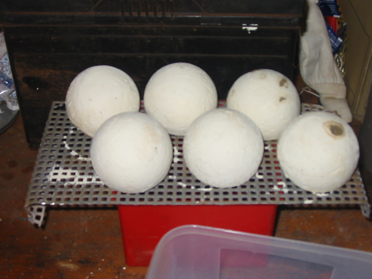
Once the cement had cured, I removed them from the sand molds, and cleaned them up, and sealed them with sealer undercoat paint. I had a hiccup when two of the eye rolled whilst the paint was drying, and stuck to the benchtop, when I pulled them off, the paint pulled out of the cement - this was a warning of what was to come.

Maybe the cement was old, maybe removal of the aggregate did something, maybe the phase of the moon was wrong, maybe the mix was too wet, maybe, maybe, maybe - whatever the reason, the eyes were too fragile. I found I could "cut" them with my thumb nail, and I accidently dropped one of the eye-plates when it was loaded with the eyes, and the eyes flew apart. (see photo below)
Based on that, I decided cement eyes were not going to work. I retained the eye fixtures, plates, and started looking for a better method. What worked was only a minor deviation from this plan, but it worked well.