Sunday, April 10, 2011

Taig lathe cabinet - drip trays and panel beating

This article covers the construction of the drip tray (first and second attempt) and touches on the panel beating methods I used

As mentioned in the article regarding the frame, the objective of the lathe base was to have a substantial piece of metal which was thick enough to support drilled and tapped holes, magnetic (for use of mag-based tool stands), and to help dampen noise. Thinking I could do this by building a drip tray out of 4mm steel, I made a tray by scoring and cutting the sheet, and then bending and welding it up.


Figure 1 - pieces of 4mm sheet scored and bent


Figure 2 - 4mm sheet welded up to form drip-tray #1


Figure 3 - resulting drip tray from 4mm sheet - distorted and not flat

BIG PROBLEM - the resulting tray buckled during welding and would not provide a flat base. no amount of cussin' or hammering would fix that. - on to Plan B.

Plan B was to use a thinner metal to make the drip tray, and then use a separate sheet to form the solid base floor. The frame was built to support this design, and the base sheet cut and fitted. From that sheet, all other measurements for the drip tray were derived.

The drip tray is made from colourbond "sign-white" - a thin sheet metal coated to prevent rust (some kind of zinc-aluminium coating) and coated in a bonded white paint - it's used by sign writers to make shop signs - hence the name. The other side is a pale grey colour, and this became the visible side since it was easier than trying to remove the old vinyl lettering from the white side.

My source of sign-white is a number of discarded signs which I obtained soon after moving to this town. The frames for the signs quickly became stock for building a myriad of doors, shelves, etc, and the panels have become door skins, guards, and a number of other tasks. This lathe drip tray commenced the use of the last full sheet.


Figure 4 - commencing the folding of the drip tray (#2) - forming the wired edge

Since I don't have a pan or finger brake (yet another project yet to start) , I improvised using tube and angle iron clamped together (often the tube was one side of an old table frame). The "mallet" was a piece of pine timber, and a piece of 2"x 1/4" flat bar was used as a flatter to help crisp up the edges. I formed up a wire edge for the edges of the tray where hands would touch by folding the sheetmetal around a strip of 3mm x 25mm (1/8" x 1") strip and hammering it flat with a mini sledge hammer.. after everything was folded up, this gap was then closed up to complete the wired edge.


Figure 5 - completed drip tray with wired edges for safety

This method of folding was used throughout this entire project - drip tray, drawers, trays, control cabinet - all fashioned with bits of tube or angle iron, 3 clamps, a piece of timber (with or without a flatter), and a pair of ear muffs to drown out the noise.


Figure 6 - completed drip tray and back board


Figure 7 - Rear view of back board showing overlap

Next article will cover the swarf gate and accompanying swarf drawer.
Still to come:
Drawers, electrical circuit, "home made" switches, control panel

Friday, April 8, 2011

Taig Lathe cabinet - base frame

The frame of the lathe stand

The frame was built based a size calculated to permit the Taig lathe to be mounted with enough room to allow the mounting of a motor, space for changewheels, backgearing, control space for the leadscrew control, and any accessories I planned including a taper turning attachment and profile copier.
 

Figure 1- Base frame with headstock reinforcing

The overall baseplate dimensions became 500 x 850mm (20 x 33.5"). The baseplate became the core of the design with a sheetmetal tray built to sit under it with a lip coming up from the front and sides, and an extended lip coming up at the back making a swarf tray capable of containing swarf or coolant.


Figure 2 - Base frame with drip tray and top sheet

The frame was welded up from 20x20mm (3/4 x 3/4") angle iron, or tubing from the scrap pile.


Figure 3 - Base frame with backboard frame attached

The Taig lathe is a cantilever bed lathe with a foot under the headstock. To provide a strong stable mount for the lathe I welded a piece of 4mm (5/32") into the base. (shown in Figure 4) This means the lathe is mounted to 8mm (4+4mm) of steel, whereas the rest of base will have a thickness of only 4mm. I deemed 4mm as thick enough for magnetic bases, or drilling and tapping into, whereas I felt it prudent to have it thicker under the lathe foot, and for mounting the motor assembly.


Figure 4 -Base frame from rear, showing angle iron brackets for back board, and reinforcing sheet at headstock

The backboard for the lathe stand adds 560mm (22") to the height of the stand and runs the full width of 910mm (36"). The backboard is attached to the baseframe by some bolts mating the board to some angle iron brackets.(refer Figure 4)

The frame contains room underneath the baseplate assembly for drawers - the height of which is 100mm (4"). The drawer widths are governed by the spacing of the stiffeners added to support the plate under the lathe foot, and a small offset at the tailstock end to support the E-stop. The space behind the E-stop is used to house a "swarf drawer".


Figure 5 - Bare frame with drip tray and top sheet removed, backboard frame attached.


The frame has 2 fold-away handles attached for moving the lathe - these are located at each end of the base.


Figure 6 - The fold away handle at the tailstock end of the base frame

The backboard was clad with a sheet of polycarbonate approximately 6mm (1/4") thick (a salvaged shop display shelf when the local postoffice was renovated), and a piece of colourbond "signwhite" from a salvaged shop sign. The sheet of polycarbonate served 2 purposes:
a - the additional thickness stood the sheet of colourbond away from the frame at the bottom edge permitting the lip of the base drip tray to slide behind it - preserving the sealing of the tray assembly, and
b - the additional thickness added stiffness and "meat" to the backboard providing substance for screws to engage with, and to dampen any movement in the colourbond sheet.


Figure 7 - clad backboard - rear view.

A few other features are in the frame, but those will be elaborated upon during the articles describing what they support.
Overall dimensions - 710 (H) x 550 (D) x 910 (W)  = 28" x 22" x 36"

Thursday, April 7, 2011

some homemade tools - pin wrench and floor scraper

The PC is now working (sorta) - the original motherboard died and took with it 2 of the hard-drives. A substitute motherboard was sourced on Ebay which should have taken the existing memory, CPU, graphics card etc... The motherboard was brand new, but over 5 years old. Basically it didn't last too long - failed in a different way and I was fighting a losing battle trying to repair this "on the cheap"
The "new" PC is simply a new motherboard ("Mainboard" as I was told by the sales guy) with new CPU, RAM and this also entailed a new OS since I exceeded the 4Gb of memory. I still have a few teething problems with my PCI SATA2 card, but I am working on it.

This article covers a few things I had to build during the outage on the PC.

Super Scraper
First is a tool for chipping cement off a concrete floor. There are floor scrapers available to taking plaster off floors, but this tool will remove tiles, cement, lino, cats, whatever you point it at. The secret to this tool is the heavy duty blade, coupled with it's weight.


Figure 1 - The super scraper leaning against the shed door

The blade is a bricklayer's bolster - a broad "chisel" which can be picked up in the discount tool stores for around $15. the bolster is modified by removing any rubber handle/covering, and then welding the handle to/inside a pipe handle of around 1500-1800mm (5-6') long. I deliberately choose heavy walled pipe for this job since you want a fair bit of weight in the tool. Since this one was made away from my scrap pile, a short length of thicker pipe was used to form a socket, and then a slightly thinner pipe was inserted to achieve the desired length.


Figure 2 - The head of the "super scraper"

The tool is used by simply sliding/ "driving" it along the concrete floor at an angle of around 45 degrees s the blade skims along the floor and the weight carves the "stuff" off the floor. A nice touch is to close in the other end of the pipe handle so there is no chance of cuts on any burrs or edges. It seems to self-sharpen as it wears on the concrete, but the bolsters tend to be pretty tough and don't wear that quick. This one was made to help a friend remove the leveling cement from under the tiles in his kitchen renovation. Prior to handing it to him, it was tested on the apron of my brother's shed where it removed lumps and cement dags with hardly any exertion.


Grinder Spanners

Another tool I had to make was some replacement wrenches for an OLD 9" (230mm) angle grinder. This grinder is an heirloom, and is so old it doesn't have spindle locks or any form of softstart. This means the spindle torques up really fast, and this seizes the retaining  piece on. I modified an old 7" pin wrench and 17mm spanner to undo the retainer in the past, but during some work the retainer became so tight the pinwrench failed during attempts to undo it.


Figure 3 - old wrenches alongside new wrenches - the ruler is 300mm (12") long


Figure 4 - old wrenches which failed

I made a new pin wrench using 1/4 x 1 1/4" flat bar with some grade 8 bolts filed down to make the pins. (4.6mm diameter on 28.1mm centres) The handle to this new pin wrench is twice as long as the original and once used the cheap modified 17mm spanner started bending. More scrap steel and I made a heavy duty 17mm spindle spanner.


Figure 5 - bolts used to provide pins in pin-wrench


Bonus Shop Tip - Cigarette Lighter Parts


Figure 6 - Disposable lighter found on road - cracked and empty

I walk the dog each day and often find discarded broken cigarette lighters. I usually pick them up and take them home to pull apart. What's worth having in a cigarette lighter?


Figure 7 - parts inside a disposable cigarette lighter

There is 2 springs and a "jet" which can be useful. The springs are a useful size for making detents in small tools, and the longer flint propelling spring is a size which is sometimes found in rifle ejectors. I've only started collecting the jets since I figure I can use them to solder into larger brass pieces instead of trying to drill such a tiny hole - useful for a burner in my project list.

Next articles will be the construction of the lathe stand.

Sunday, March 13, 2011

Taig Lathe Cabinet - Motor Mount and unloader

I'll start documenting the build of the lathe cabinet using those photos still on the card in the camera (the other photos will have to wait until after the PC is rebuilt)

The Motor Mount
The original lathe stand used a jackshaft mounted on a wooden slide-way for a clutch, and speed control was limited to the cone pulleys on the motor/jackshaft - and then the standard Taig 6 speed cone pulley.

The new motor system would have the motor speed controlled by a VSD (Variable speed drive) giving infinite speed control over the range of 0-100%.
I still wanted a clutch (unloader) so I looked at various designs used by others and cobbled up a version of my own.

The belt tension aspect of the motor mount is loosely based on a design shown on Nick Carter's website. (www.cartertools.com)
His design uses rods for alignment, and a threaded rod for adjusting the position of the moving member. My design uses slots cut in the mount for alignment, and a threaded rod for adjustment.
The basic structure is made of two pieces of 50x50x3mm angle iron (2" x2" x1/8") welded together to make a channel 100mm wide and 50mm deep (4"W x 2"D). the length of the pieces is approx 200mm (8")

I then cut 2 pieces of 50x50x3mm angle iron at around 300mm (12") long and cut slots about 12mm (1/2") from one edge. The slots were a clearance fit on standard 6mm bolts. (Slots were cut using drills to mark the ends, then 1mm cutting disc in between)

Corresponding holes were drilled in the piece made earlier in the description, and 20mm (3/4") bolts were tacked into place so the threads extended out through the slots.
End pieces were measured and made up to close out the end of the longer pieces, as much for stability, but also to support the threaded rod used for the adjustment.
The moving part is driven by a nut which was threaded in, and then tack welded to the underside of the moving part.Nuts spun on to the threaded rod, and welded in place became the thrust surfaces for the rod's action, and one nut was welded in place out the front of the unit for adjustment purposes.


Figure 1 - base of motor mount - sliding parts.

The pieces already described do not actually mount the motor, instead they provide a base which can be adjusted. The part which actually supports the motor is a hinged channel (cut from the side of some 100x100x3mm square tubing) so it actually 100mmwide, and 15mm deep.
A corresponding piece is fabricated from 4mm plate to sit atop the moving motor mount part made earlier, and to support the channel piece just described. The channel piece supports the motor by means of 2 slots cut in the channel at right angles to it's long axis - these permit adjustment of the motor position along it's shaft axis.

The channel is hinged onto the mount plate, and a cam is placed near the mount hinge to change the angle of the channel. The cam was built by cutting an approximate shape from 4mm sheet, then  tack-welding a 15mm wide strip of sheet around the cam surface for wear reduction. The cam has a position where the "lifting effect" is stopped - this is the position where the motor is tilted back away from the headstock of the lathe.


Figure 2 - the built up cam which tilts the motor mount channel.


So the overall structure is:
the motor tilts forward and backward within a range of motion governed by a cam (35mm = 1 1/2")
which sits atop a sliding mechanism which adjusts belt tension over a range of 75mm (3")
The motor can also move along it's shaft axis by 25mm (1") via the slots its mounted in.

The cam is operated by a wire lever about 250mm (10") long located well out of the way on the LHS of the cabinet.


Figure 3 - completed motor mount assembly

A standard steel ruler pinched under one of the slide nuts was used to test the range of the tilt mechanism


Figure 4 - Motor mount system in the unloaded (belt tension released) position.

The recorded range of motion was approximately 35mm (1 1/2") between unloaded (no tension) to the loaded (tensioned) position.


Figure 5 - Motor Mount in the loaded (tensioned) position.

Why have the facility to drop belt tension via the lever?
#1 - ability to leave the lathe when not in use with the belt un-tensioned to prolong belt life
#2 - easier changing of positions of the belt on the 6 speed pulleys
#3 - less chance of driving the motor when moving the spindle by hand (new motor is a PM DC motor which would act like a generator if I spin the chuck by hand)

So based on this design whenever I change the belt, I would place the belt on the appropriate pulley range and push the lever up into the "loaded" position.
I would then use a 17mm socket to adjust the threaded rod and move the sliding part so the belt tension was where I wanted it.
Then I would use the lever to reduce the loading, and adjust speed ranges accordingly.

In testing, I have found the flat section on the cam is sufficient - I can "feel" it click in through the handle, and the tension stays constant during use.


Next couple of posts:
I have photos of the frame construction, basic sheet metal work, and the construction of the control panel i can access. It doesn't cover much of the control electrical system, but does cover the fabrication of the switches, and the panel-work itself.
Monday, March 7, 2011

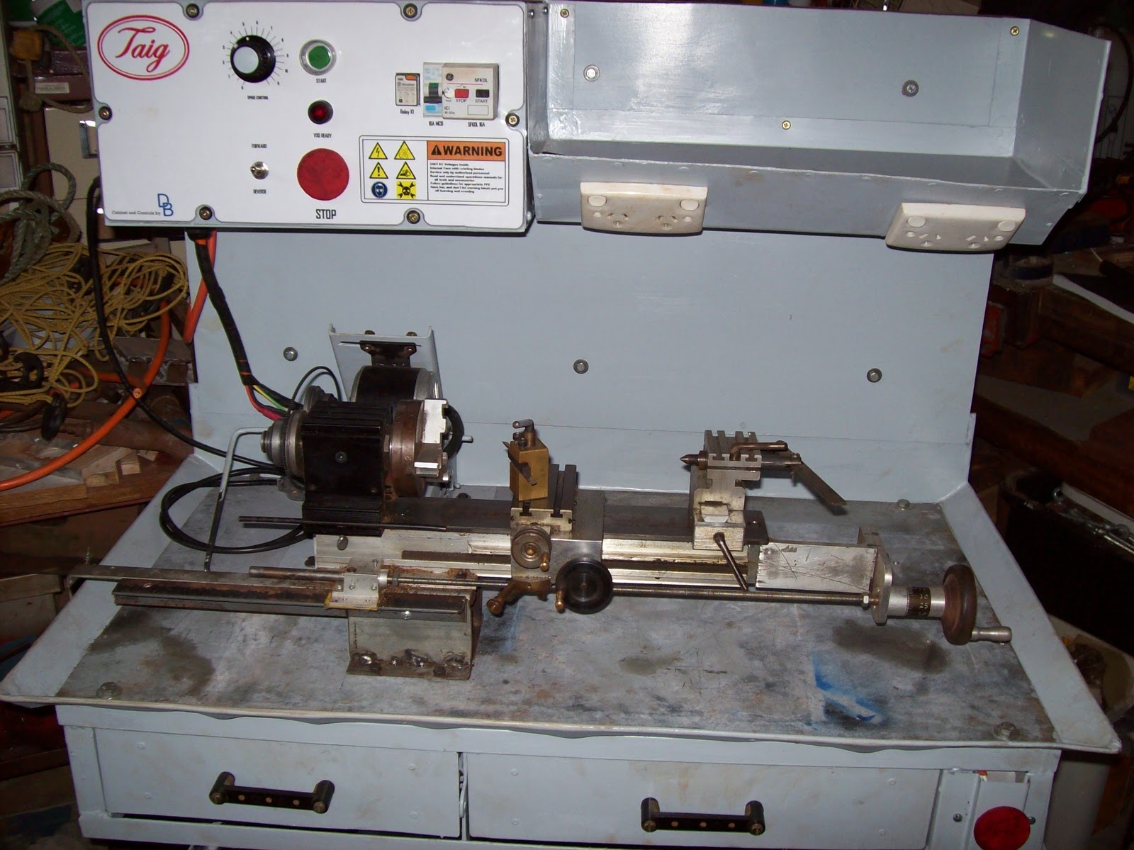
Taig lathe cabinet - completed

Today I took advantage of some time away from work during the public holiday to bolt the Taig lathe to the new stand.

Some history...

Figure 1 - original lathe stand

I bought the original Taig lathe from an amateur pyrotechnician in Brisbane in 2001 (or was it 2000?) The motor which came with it was a salvaged unit from a washing machine.


I modified the motor mount to retain the pillow block and 1/2" shaft, but mounted the motor and jackshaft on a set of sliding mounts which gave me a clutch in the form of a "belt unloader".


Figure 2 - motor mount and jackshaft on sliding mechanism

I put a drawer underneath the 18mm (3/4") MDF top sheet and used it this way ever since. In the meanwhile a removalist broke the jackshaft mounts, the motor board started a gradual twist (compensated for by inserting popsticks under the motor mounting), and the bearings in the motor started to fail.


Figure 3 - tail stock view of old stand

The motor controls (on-off switch) is mounted in the front of the white icecream container screwed to the baseboard - inside the icecream container is the start capacitor and the wiring out to the motor. - real high tech.

Over the past 5 years I commenced modifying the lathe by adding a leadscrew and halfnuts, converting the tool post and tail stock socket screws to thumb bolts, and building accessories.


Figure 4 - the conversion of socket screws to thumb bolts

So after essentially 10 years, this 12-14 year old lathe is getting a new cabinet and drive

That was the past - now here is the future...

Figure 5 - the new cabinet with Taig lathe in place


Electrical highlights
300W DC PM motor driven via a PWM VSD (Pulse Width Modulated) (Variable Speed Drive)
NVR and E-stop safety circuitry (No-Volts Relay)
4 switched GPOs onboard


Powered from a single 240VAC IEC power cord


Figure 6 - electrical cabinet

Mechanical features
Metal cabinet with enough "meat" to permit drilling and tapping accessories anywhere I want.
Swarf tray with gate in floor
magnetic metal base for DTI, etc
motor mount has a "belt unloader"
All painted up in "Bender gray" except the 4mm thick metal baseplate

The motor mount is loosely based on the Nick Carter design, but modified for my purposes with a cam operated unloader mechanism.


Figure 7 - the motor mount in the "unloaded" position

The control panel represented an interesting amount of work which will be covered in greater detail later. one of the fun parts was the logos and labelling - the frustrating parts was doing the wiring to a suitable standard which permitted easy construction, and repairs.


Figure 8 - close up of control panel

In all, about one month's work over weekends, and the odd day here and there (mornings during shift rostered days.) - estimated total labour time would  be 100 hours
The wiring took about 3 days since I had to redo some of it when my neighbour offered some advice on how to make it better for someone else to fault find in.
Everything except the motor and some electrical components was either constructed, or salvaged - the out of pocket expenses were around $200, and a large chunk of that was for the power supply.

I will do up some articles which highlight the construction process, with focus on the various components/ skills, but in the mean time I'm going to enjoy using this "reborn" lathe.

Sunday, March 6, 2011

Making some dolls houses (CBFT training aid)

My ERT trainer mentioned once that as part of Compartment Fire
Behaviour Theory (CFBT) training, we can observe the phenomenons
(neutral plane, pyrolysis, etc) in a training aid called a "dolls house".


Figure 1 - cutting up the chipboard

A dolls house is made of chipboard and is nominally 400 x 400 x 400 mm  in size with a door way cut in one side.
The plans called for 16mm chipboard, but all the local supplier had was 18mm - no difference, just means the internal volume will be slightly less... with thicker walls the burn may take more time before the house falls apart.

Basically I cut up 2 full sheets using a circular saw, and then nailed the pieces together to hold the bits together whilst the "liquid nails" (construction adhesive) set up.


Figure 2 - the doorway cut into strips which can later be broken up as cribbing


I cut up the left over pieces to make 6 small "tables" to simulate internal furniture, and the remaining timber was cut into small pieces to kindle the internal fire ( pieces called cribbing are all about 1/4" wide, and the full 18mm thick)


 Figure 3 - open door to dolls house with "ikea table" inside


I also had to make a stand to place the completed dolls house at around chest level. I had a cast iron base from a large industrial fan which I modified to take a base for the dollshouse.


Figure 4 - completed stand with base for dolls house

During the construction of the stand, I had to undo a bolt on the stand which was slightly rusted - when the nut/bolt rust finally broke free, the spanner spun through and crushed my ring finger splitting the nail from side to side. Hurt like blue blazes, and bled like nothing I've seen in ages. After a few hours the bleeding had stopped and this is what it looked like...


Figure 5 - injury to ring finger


Job done as delivered to the trainer.


Figure 6 - completed houses and stand


Next posting/s should be the completed taig lathe cabinet, and construction articles.

Saturday, February 5, 2011

Taig Lathe Stand/Cabinet - introduction

The current project...
My Taig lathe has been residing on a sheet of 18mm MDF for the past 10 years. The sheet has a wooden drawer built in underneath it, and a clutch/ jackshaft system for speed control. I will put a photo up in this series of articles, but not yet, this post is more a "preview".

Basically the old base (lathe stand) works, but it has limitations and problems. Some of the problems are the result of a certain removalist, some the result of bad design on my part, and most are simply the result of cutting corners due to cost constraints. - whatever the reason, it's time to make things better.

I'll do up a series of articles covering the design and build (mechanical and electrical) later, but for now here's some progress photos and a brief note of some features...
Lathe stand/ cabinet features:
full length/width drip tray
2 lockable equipment drawers under the drip tray with full extension
removable swarf tray
swarf gate in drip tray for dumping swarf
removable back board
4 switched GPO's (power points) with MCB
adjustable motor mount with belt unloader (clutch)
fold in carry handles
magnetic base with enough thickness for tapping holes if needed.
enough room to permit/ support my planned projects (backgear, change-wheels, taper turning attachment, indicator bases)

Motor controls:
24VDC 500W PWM VSD with reversing switch
16-20A over current protection
NVR (No Volts Release) circuit with additional e-stop at tail stock end


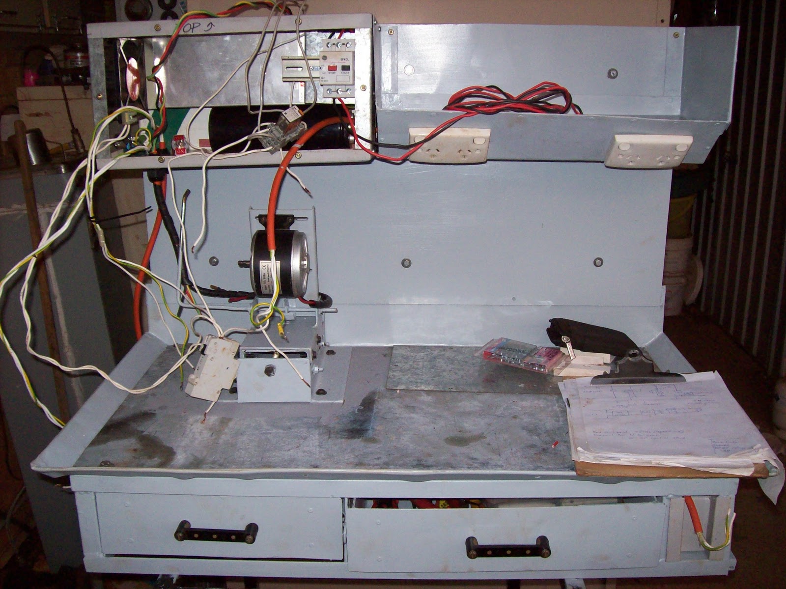
Just  waiting on the postman to deliver a few parts and this job is finished. The VSD cabinet (LHS rectangular section) contains:
500W 24VDC PSU (courtesy surplus parts online)
6800uF capacitor from a Seimens VVVF (for smoothing)
125mm fan (with some trickery in the ducting) for forced cooling
PWM circuit (with heatsinking)
control switches (Start, Stop, Speed control, reversing switch)
IEC socket with filter

DIN mount rail containing -
16-20A SFKOL overload protection device
NHP Terasaki MCB for isolating all 240VAC circuits
Industry standard relay mount and relay for NVR circuit
The DIN mounted components are accessible through the front panel (for resetting, or fault finding)


Both drawers are accessed from the front, on ball bearing slides with full extension - no excuse to have things lost in the back of the drawer again.


The removable back board supports the electrical circuits, and a tray for storing things during work - a work light will be attached to this backboard as well.


The range of travel in the "unloader" mechanism is shown here (the distance between the shaft and the vertical steel ruler - about 35mm (1.5")). The adjustable motor mount is shown midway through it's 100mm (4") of travel.


A photo from the tailstock end of the cabinet showing the tray mounted on the backboard - the rectangular holes visible in the slanting face are for the GPOs. The tray has a false floor and is sealed so the GPOs and cabling are protected. The GPOs were mounted in this manner (downwards sloping face) to provide easy access, but also make it impossible for swarf or coolant to fall into the outlet holes.

The materials used is basically salvaged sheet metal - some 4mm gal sheet for the load bearing areas, and sign-white (colourbond) for the rest.
The frame is a hotch potch of 25x25x3 angle, and some 25x25x1.6 square tubing.
All sheet metal bending (that worked - see future postings) was done using metal clamping with judicious use of hammers, wood blocks, and muttered cussin'
Most of the electrical parts are salvaged, however the power supply, and PWM section are purchased/ built  - all other parts removed from salvaged equipment (even recycled some bus mounts from a switch board to make the drawer handles)

The techniques, design, and details will be covered once I get the main computer fixed (power outage cooked one of the bridges in the mobo - lost the O/S drive and a few other peripherals), and few other demands on me at this time

Next update will most likely be in two weeks time - the pictures are already taken, it's just time to type, format and upload.