Showing posts with label bricolage. Show all posts

Saturday, May 8, 2010

Customised Meter Case - & musings

Before I get into this little project, I just want to say how happy I am Daria is finally coming out on DVD. I've bough the various box sets issued over the years by various companies, but all of them were simply DVDs cut from the "Sarcast-a-thon" showing, complete with the original music, and various station markers, and glitches.. but still Waaayyy better than nothing. But come 11th of May 2010, MTV is releasing the Daria DVD box set - still no news on the music, but again - better than nothing. I'll be buying my copy from Amazon due to the price - Here


The other musing was trying to pick a suitable photo for my profile. There was no way on earth I was going to put a photo of myself up there (It's offend the internet spirits for sure) so I was thinking about suitable "archetypes" I could use... some of the candidates included "Q" (Desmond Llewellyn) - from the James Bond franchise, "Tobermory" from the Wombles, Macgyver, Eeyore, and Alastair Cookie, and I even considered Erik (the Phantom of the Opera), but then I kept coming back to this one choice.... This man displays all the qualities and attributes I'd associate with - quick witted, intelligent, inventive, and a great many other characteristics I wouldn't dare include on a resume such as devious, megalomaniacal, and unassuming dress sense. He's Graeme Garden from the Goodies - if you missed out growing up with the Goodies in your life, take the time to get some episodes and see what the fuss was about. If you know the Goodies, you'll know and love "Graybags", even if you associate more with Bill or Tim.


On to the project...

I use a Fluke 179 DMM (Digital Multi Meter) as part of my work, and carry a number of leads, clips, and spares for the meter. One of my co-workers had a case which had the meter on one side, and the spare leads on the other, but I could not find anyone offering the case, and he'd had it for years. I got sick of carrying two cases to jobs, and so decided to make my own case.

I started with a CD wallet for the local Kmart store (big variety chain store - viz Target, or WalMart). The wallet had a zipper around three sides, and a "clam shell" design based around a firm material covered rubber. All up the case was about 50mm (2") thick when stuffed with cardboard.
The CD wallet is shown below...


I removed the CD sleeves, and salvaged the velcro strips used to hold the sleeves in place. I purchased two "cheap and nasty" pencil cases ($1 each) just to get cheap zips, and purchased a cheap roll-up cutting board for the plastic ($3 for 4 boards). The fabric is from some old work shirts that had become too ratty to wear in the shed.
I sewed up a "pouch" to sit above the meter which holds the spares for the meter (fuses, battery, holding clip)


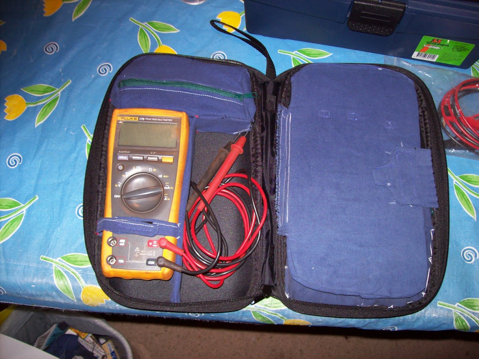
The divider which holds the meter to the LHS (Left Hand Side) of the case is a piece of the roll-up cutting board sewn into a sleeve of cotton fabric. The salvaged velcro is used to secure the meter into the case. The spare space on the RHS of the meter is used to roll the connected leads in for easy use.

The contents of the top pouch are shown below... the brown wire is the K thermocouple used by the Fluke meters for measuring temperature.


The RHS of the CD wallet was separated from the meter section by a panel made from more cutting board plastic encased in another cotton sleeve. The panel is retained by a fabric hinge stitched in the middle of the wallet (White lines of stitching in photo above), and held in place with a velcro closure on the RHS edge. With the velcro closure opened, the panel can swing over the meter to reveal...


The spare leads are vecro'd in pairs to the top section of the panel. The thin black velcro was the last of the velcro salvaged from the original CD wallet.
The pouch sewn into the lower half of the RHS shell contains the spare tips, and probes. The pouch is a simple sewn pouch with another "pencil case" zipper for a closure.


The entire meter case took about 2-3 hours to make including the cutting, sewing, and hand stitching the pouches in place. I've now been using the case in the field for about 6 months and had no complaints about how well it's met my expectations.

A few sewing notes...
threads were typical 100% polyester threads used for normal sewing.
Sewing needle was a normal Smetz universal needle (#15 from memory) and it handled the three layers of cotton, plus the 1mm of cutting board plastic fine.
I used my Toyota sewing machine for this job since it is my current "work horse" machine. I have an old Elna "Air electric", and a Husky 4 thread overlocker, but those only get used when needed.. the Toyota is my "day to day" machine.


I'll post a review on Daria once I have it my hands!!! - Come on Amazon...

Sunday, April 25, 2010

welding cart

The welding cart was built to overcome the issue of always working on the ground. For some tasks, the cart is not suitable, and the welder is removed from the cart, and taken to the job, or the cart is simply left near the job, but the earth lead is disconnected from the cart, and clamped to the job.
The welding cart offers another advantage - one of a "large earth"... All my welding experience up until I built the cart was based on attaching the "earth clamp" to the piece being welded. Sounds good, but sometimes it's easier said than done. I had seen other people clamp to a large sheet of steel, then drop delicate work on the sheet, and use it's contact with the sheet as the return path. The entire cart is like that sheet of steel. The return clamp is attached to the cart (in my case by the clamp being attached to a tab on the underside of the table) so anything I place on the top of the table can become part of the current path, simply by it's electrical contact. This simplifies any delicate work considerably, and allows repositioning without fighting with the return lead.

I'll talk more about the welder itself in another page, but it has been considerably modified to make it more usable for the kind of things I want to do with it.

The cart was made from salvaged materials. Most of the sheet metal was cut from a discarded instrumentation cabinet. the steel is all 1.5mm (about 1/16") thick, and was powder coated/enamelled. The cabinet was basically cut so the top and bottom portions became the top and bottom of the cart, but the sides were replaced with other material.
The main structural components (frame, uprights, etc) were made from a rolled shape which I got from the tip. The cross-section resembles a squared up letter C, and it came in lengths of 1200mm (4') with grey paint on it. I believe it was some kind of packing material for shipping motorcycles, but I really can't be sure. The steel is 2mm thick, and the C shape is basically 30-35mm wide, and 19mm (3/4") deep. The slot on the open side of the C is 10mm (3/8"), and a 3/4" square tube will ride inside the C section if one corner is protruding through the slot (I used this exact concept to make the leaf folding mechanism)


Construction was basically determining the finished height, and then making up the side frames to that height with the top member equal to the width of the cabinet top.
The frames were welded to the top and bottom pieces, and some cross pieces were cut and welded in to form a "shelf" in the middle.

The middle shelf does not extend across the entire width of the table, since I determined it would be prudent to have the full depth of the table available on one side for hanging cables. Additional cross beams were cut and welded in to form the sidewall of the middle shelf, and some hooks were welded in on these beams for hanging cables.


The original build on this cart had four wheels, one at each corner, but within a very short time, I determined was troublesome - firstly for the issue of uneven ground, but mostly since the cart would move under the forces of grinding, or other metal abuse activities. The front wheels were cut off, and some 3/8" nuts were welded into the front pillars. Some 4" long cup-head bolts were screwed into these nuts, the heads of the bolts forming the feet for the front of the cart. A telescoping handle was added into the shelf beams, to assist in lifting and moving the front of the loaded cart. The telescoping handle is nothing more than a piece of the C section steel tubing, with another piece of 3/4" square tubing inside it, some stops welded in, and a "handle" to make it easy to pull out.

The telescoping handle can be seen just above the top PVC tube, extended out approximately 6"

The top of the bare cabinet was about 400mmW x 500mmD, and adding the widths of the two support frames either side only added another 70mm to the overall width - not nearly enough room for any serious fabrication. A means of making the table top larger was required.
One of the cut away sides was stiffened up by welding a piece of "C" tubing at each end, the original folded edges were sufficient for the sides since the folds were 3/8" deep, and 3/8" wide, 3 sides of a perfect square.
Some hinges were padded out, and screwed in place for the drop leaf, and the salvaged rear axle of a dumped lawn mower was used for the hinge of the brace. The ends of the axle were trapped in some short pieces of 3/4" square tubing which was tacked under the sheet metal leaf.

Photo taken from underneath the raised leaf, showing the brace, vertical track, and it's joints.

The other end of the brace is bolted to a "shuttle" which runs in a vertical track. The shuttle is nothing more than a piece of square tubing running in another piece of C tubing, with a tab welded to it for the brace to bolt onto.
When the leaf is dropped, the shuttle is in the bottom of the c section track, but when the leaf is lifted into position, the shuttle moves upward, and trips a weighted pawl which prevents the shuttle returning past it. This pawl keeps the lifted leaf in the "up" position, level with the permanent table top. The pawl is released via a lever at ground level which can be activated by the operator's foot.

The locking pawl as viewed from under the shelf. The release mechanism, and counterweight is operated through the 3/8" rod which acts as an axle for the pawl. All joints are simple clearance holes through scrap steel, nothing fancy.
Top photo - leaf lowered

Photo of leaf raised


The welding cart has evolved a little over time, the middle shelf had some lengths of PVC pipe added for providing storage for welding rods (2.5mm and 3.2mm), and a block of wood with some holes drilled through it was added for holding the "live" electrode (handpiece) in an insulated holder so I could put the handpiece down during a job, and not worry about current flowing (the lesson on that effect was most uncomfortable).

The 3/8" cup head bolts failed recently (see Hose suspenders page) when I wheeled the cart out in the street so I had enough room to turn a 4m (12') length of 3/8" square rod through a jig clamped atop the welding cart. It was during the repairs that these photos were taken. The 3/8" bolts, and nuts were removed, and replaced with some 20mm (~3/4") anchors and nuts. I don't know what the anchors were for (part of a toolbox full of junk which I found on the side of the road - it's amazing what falls off trucks around here), but it's nice to use some of them up.


That's about it - I know I took better photos during the construction of the cart, but I don't seem to be able to find them. I know the cart looks rough, and I'm really not in the mindset to go nuts painting things like this when all they do is get dragged between the shed, and the job. I paint things which will spend more time "sitting" than working, unless painting is needed to protect the "thing" - given this cart is my biggest workhorse, I don't see the point painting it. If fact, I have to periodically run the grinder over the top every month or two to remove any rust, or paint which would stop the current flowing through the top and whatever workpiece is on it.

A lot of what was built when I first set up here was built from scrap I collected from friends at work, and the local tip (Salvage). I'd just moved to start this job, and disposed of all my building materials for the move. You will find a lot of what I describe and show in these pages will be made from salvage/ surplus materials. Some if it is my desire to save money, most of it my desire to reuse materials, and find uses for "junk". I read shop notes books from the 1900's for fun, and do not subscribe to the throw away mindset that many others have.

Friday, April 9, 2010

Grabby & Squeezy - Hands part 1

Grabby and Squeezy - these are the names of Bender's hands.

Knowing how important Bender's hands are to him, I spent a lot of time trying to figure out the best way to build them.

I'd been collecting his fingers for ages - the fingers are discharged CO2 cylinders from life jackets. I tripped over some at work one day and recognised the shape. The guys on shift, and maintenance saved them for me and I ended up with enough to make 4 hands. I'm retaining the spare fingers in the hope of redesigning the hands in the future.

As with everything else in Bender, I started with scrap 4mm galv sheet. I marked out a number of disks, 2 to match the diameter of the arm pipe, 2 to match the inside diameter of the hand, and 2 to match the diameter of the flared hand. The largest plate (flared diameter) was then marked out with 3 radially spaced holes to match the diameter of the Co2 cylinders. (finger plate)
A central hole was also drilled in all plates for the retaining bolt.


The above photo shows the components which make up the hand. From left to right across the edge of the welding table the parts are; Arm plate with captive nut, wrist plate, captive retaining bolt, pipe spacer, finger plate, 3 fingers.
The retaining bolt has had the threads nearest the head undercut so the bolt can spin in the wrist plate and not fall out, or bind. The spacer pipe seperates the wrist and finger plates.
The pieces above the components on the table include the made up shroud, but that will be discussed more in the next page (part 2).


The components assembled. The arm plate has been welded to the end of the arm, the wrist and finger plates welded to the spacer pipe with the retaining bolt already captive in the wrist plate prior to welding. The fingers were set through the holes, with a moderate degree of flaring, and then welded in place. Another view of the the assembled hand structure is shown below...

Part 2 of "Grabby and Squeezy" will cover the construction and fitting of the shroud, and placing the hands on the arms.

Wednesday, April 7, 2010

a few more pictures of Bender


So what more do I talk about now he's pretty much completed...
The head can rotate 360 degrees, and is positively retained.
The shoulder joint can rotate 360 degrees with stops at 8 locations.
The wrists can rotate 360 degrees as well.
The legs, and waist are rigid.

The wall thickness of the body metal is ~4mm (between 1/8" & 3/16") - the original wall thickness of the propane cylinder (44Kg, 100lb).

The head is made from an old NuSwift 9 Kg (20lb) Dry Chemical Powder fire extinguisher with a steel wall thickness of 1/8" (~3mm), and retaining the original bronze valve fitting for the antenna attachment. The boss for the pressure gauge was cut out, and replaced with a patch cut from another extinguisher.

The teeth panel is made form some colourbond offcuts - pretty springy sheet typically used for the manufacture of roofing/ fencing panels. It's a simple flat rectangle which is then rolled and placed inside the head, with the painted surface viewed through the open mouth. The springy-ness of the steel makes it press against the inside of the head, and conform to the curve wonderfully.

The dimensions were taken from a number of places, including a die cast model, a windup toy, several pictures from the internet, and the "How to Draw Bender" feature hidden inside one of the DVD discs. Even when he was complete, he looked as though his legs were too short, but I triple checked, and it's right - I guess Mom's friendly robot company never adhered to DaVinci's proportion model when they designed him.

I'll commence the construction photos shortly - if there's detail I miss that you want explained, let me know.

At this stage I don't plan on issuing dimensions other than the basics. I am happy enough to detail the construction, colours, etc.