Showing posts with label futurama. Show all posts

Friday, June 17, 2011

Field desk - part 5 - Painting and trim

The painting and trimming of the field desk.
Painting was straightforward...
Undercoat,
filling,
masking and
top coats of "Bender grey" (the darker grey used to paint Bender's arms and legs)

In keeping with the Futurama theme, and tying in the fact that this desk is designed and made for use in electronics and microprocessor experimentation, I decided to theme the trim on the concept of the desk being a "Momcorp" product, a prototyping/ repair kit for Momcorp products using microprocessors.
From that concept, it wasn't too hard to look at this as an "Experimental Brain Surgery Kit" (Always wanted a tool box with that written on it!!!) for robots and robotic devices.

Figure 1 - Momcorp logo pages drying after clear-coating and spraypainting
I created a version of the Momcorp logo (The nicer one, not the authoritarian vertical MOM one) and decoupaged it to the front and back of the desk. I printed the logo I made on the thinnest paper I could find, then spray painted the back white to increase the opacity -  I clear coated the front to stop the ink running.

Figure 2 - Decoupaged logo on door of field desk

I then got to thinking... if I was in the year 3xxx and a technician, I wouldn't leave my travelling toolbox looking so bland. It would have stickers on it ....
  • from places I'd been authorised into (HAL institute for criminally insane robots), 
  • stickers from products (Mom's old fashioned robot oil, bachelor chow, slurm), 
  • stickers which reflected the world around me (political, social fads, social commentary, humourous), 
  • and at least somewhere I'd have my name.
Based on that, I started cruising the internet finding images from the show, and editing them into a sticker style format. I found a few in that "cafepress" site which were already done, and used their look as my template. I downloaded a few fonts, and made a few (how I made the Momcorp logo) and then printed them in my inkjet printer.
Figure 3 - several pages of "stickers" drying after painting
All of the "stickers" where clear coated over (to stop the inkjet ink running when varnished), and most were spray-painted white from the back to improve the contrast and opacity - but not all. A few of the images were deliberately scuffed and aged just to add a "worn look" to them. - given the less than perfect cabinetry, a few bumps and scratches here and there will be well and truly "in character: A couple of the stickers were not painted white from the back so they'd appear to be made from newsprint paper... just for variety.
Figure 4 - Back of Field desk with stickers applied
Stickers include: The vitruvian robot drawing, robo-fresh, the feminista bumper sticker, WWZJD.....
Figure 5 - Door of Field desk (Outer side)
several Slurm stickers, Mars University, Scary Door, a binary expression....
Figure 6 - LHS of Field Desk
Nixon's reelection campaign poster, robot oil sticker, "I love Snu-Snu" bumper sticker (who doesn't?)....
Figure 7 - RHS of Field desk
A hypno-toad sticker, a trekkie bumper sticker, robot oil ad, more slurm.....
Figure 8 - Top of Field desk, including "protest sticker"
more Slurm (it really is addictive!!!), the Earthican flag, a "Morbo" bumper sticker, HAL institute sticker, a NNY sticker, and a "protest sticker".
The protest sticker was written up in the Futurama "alien" font - it's the font used throughout the show. I won't give out the meaning, but it's a very well known sentiment amongst those whom nanny-states will try and govern.

That's it for the trim - I did have a bachelor chow sticker, but it got damaged during painting (Wind got it while it was wet) - I was going to put a DOOP sticker on as well, but it was starting to look cluttered... we'll see.

All that's left now it to show the unit with the contents in it. That article is as much for the PICAXE forum as any other groups since they helped me with the shopping list of things going in there.

Friday, April 9, 2010

Grabby & Squeezy - Hands part 2


This page covers the shrouds of the hands, and fixing the hands to Bender's arms.

The shrouds are simple conical transitions. From my interests in model rocketry, I had a tool called VCP (Visual Centre of Pressure) which contains a simple little utility for generating the development of a conical transition on paper. I used the package to develop the template for the hand shroud using the arm diameter at one end, the flared diameter at the other end, and the length of the transition being set to the height I choose (83mm to match the arm diameter, but then padded the number out to 95 so I had room to adjust things during construction).
The resulting VCP printout was then cutout, and traced onto the colourbond offcut shown above.
I added some extra depth at the narrow end of the conical section for retaining tabs, and proceeded to cut out the shape.

The first shroud has been cut out, and rolled, the second one hasn't been cut yet. Rolling the colourbond would have been easy if I had some sliprolls, but I don't. I simply clamped some pipe to the benchtop, and pulled the colourbond piece through and manually forced the curve into the metal. I repeated the bending a few times to tighten the curve, then clamped, drilled, and pop-riveted the shroud together.

This picture shows the tabs I cut for retaining the shroud. Knowing the shroud can't move towards Bender's fingers due to the conical shape, I wanted to retain the rear of the shroud by pinching it in the wrist joint. I know if I'd measured and marked everything to the highest degree of accuracy, it wouldn't be necessary, but knowing my welding, the slightest warp would have betrayed the joint, it was easier to make the shroud retained against the joint for a seamless fit.

The photo above shows one shroud fitted to one hand, the second (right) as the two pieces. A small slot was ground into the wrist plate to provide clearance for the pop rivet. All rivets were beaten down flush with the sheetmetal to reduce the protrusion, then later tidied up with bog.


The hand is attached to the arm via the captive retaining bolt in the wrist plate. Prior to welding the spacer pipe into the plates, the bolt head was modified so a screwdriver could be used through the access hole to turn the bolt. The one bolt holds the hand in place, and positioning of the hand is accomplished by loosening the bolt, rotating the hand to a suitable angle, then re-tightening the bolt.

When the bolt is tight, the shroud to wrist seam disappears. There is a small step in the diameters at the seam, but that will be disguised when the painting occurs.


Since I was out of "Ole Fortran" beer, I had to make do with one of the drinks favoured in this area. The Lemon-Lime SOLO is a nice drink, and I can see why the guys in the workshop prefer it on hot days (Isn't that everyday around here?) I know I got addicted to them after one shutdown, so now I try and limit myself to only one can per day.

So what haven't I covered yet? Still to come; antenna, head, eyes, and then painting.

Bender's foundations - feet, legs, base - part 1

The foundation, the base, what holds Bender up.

I started with the largest piece of scrap sheet I had which was 4mm thick. It's about 900x600mm (3' x2') and marked it up so Bender would be standing with his feet centered 150mm (6") back from the centre-line. I made him off-centre since I determined his center of gravity would always be forward of his center-line due to the positioning of his arms, the door being opened, and the weight offset in the head (weight of eyes, shroud).

I also decided his feet cups would not actually rest on the plate directly. I decided this based on trying to prevent rust from moisture being trapped there, and to give me the option of covering the base plate with sand, cement, or some other covering to disguise it. The gap under the foot cups is about 6mm (1/4"). So how are the feet attached to the base?

The foot cups are simply the tops of 9kg(20lb) NuSwift DCP extinguishers, appropriately cut, patched and positioned to make the feet. The NuSwifts used to have a large bronze valve at the very top containing the release disk, hose port, and carry handle. The valve casting screwed into the top of the extinguisher via a large bronze pressure fitting which was brazed inside the body of the extinguisher. In the above photo a gutted valve has been turned upside down and bolted to the base plate. A small piece of steel has been welded to the baseplate between the handle lugs to prevent the valve from turning on the retaining bolt. The foot cups are then simply screwed onto the valve from the underside with only the bolt and spacer protruding above the cup. By locking the rotation of the valve, and marking the feet ( The chalk "R" inside the cup) the feet can be repeatedly placed on the baseplate the exact same way.

The above two photos show my first attempts at making the legs from short sections of extinguishers cut and welded at angle to approximate the curved legs. - I know I could have made them straight like Simon did at asciimation, but I wanted to make mine curved since it seemed more natural and "in character". After many frustrating attempts at trying to make the legs from the extinguisher sections, I thought of a better way, and cut the old attempts away from the feet and pitched them in the trailer for the tip.


The new legs... "Captain Dan, you've got new legs" - sorry couldn't resist....
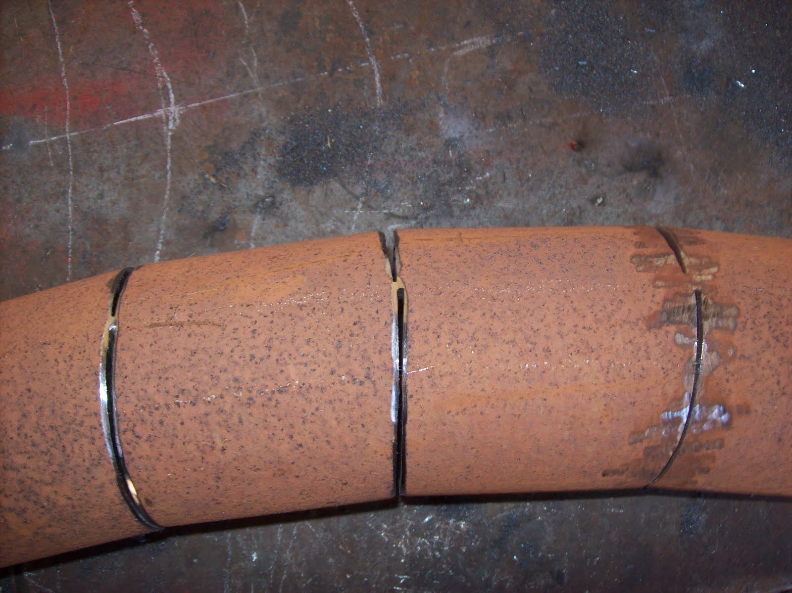
The new legs were made from some pipe I scored from some friends at work. Apparently it was leftover from some obscure job and didn't suit anything around the plant. It was an odd size - 83mm OD (about 3 1/2") and only 2 mm larger than my plans called for. I marked the centre-line of the pipe, and called that 12 o'clock. I then marked lines at 2 and 10 o'clock. this divided the circumference of the pipe into two sections, one of 60 degrees, the other of the remaining 300 degrees. I then marked out the regular segments based on the spacing being equal to the diameter. I had originally thought to have the welds visible for the legs and arms, but later ground them flush.
With the marks all in place, I used a 2.2mm cutting disk to cut the 300 degree segment lines. I then left about 1mm (1/16") of connected steel, and used a 1mm disk to cut the 60 degree segment lines. This allowed me to "bend" the pipe so the 2.2mm cuts closed on themselves, and the gaps at the 1mm cuts only marginally increased. The resulting curve is shown below, with some minor grinding to prepare for welding.


A note about my welding... I've been asked what kind of welder I have. It's a common cheap arc welder - 240VAC "buzz box" using 2.5mm SatinCraft welding rods. I'd love to have a MIG welder, but that will have to wait for another day. I did try learning how to use a MIG welder several years ago, but I'd got so used to controlling my arc by my own hand, I kept moving the handpiece and not compensating for the wirefeed. Learning to MIG is on the "to do" list, but a long way down whilst the stick welder does what I need.

Building Bender's body - part 4 - the door


The door needed to be hinged so things could be placed inside the chest cavity. I did consider using normal hinges, but I didn't want them visible from the outside - I was trying to follow the cartoon as accurately as possible. The hinges seen here were made from the same 4mm galvanised sheet I used everywhere. I made up two pairs of them, bolted them together and shaped them as one block using the grinder, files, etc. after seperating the parts, I put them back into their sets and welded in one half of the bottom set, placed the door in place with spacers (shim steel made from pallet straps) and commenced welding in the other hinge parts.


This photo shows how the door hinges inside the cavity somewhat by having the door parts of the hinge flush with the edges of the door, and the chest parts above (or below as appropriate) so there is clearance. A washer is used to maintain the spacing as put in by the shims.


Although we rarely see the knob on Bender's door used, it's always drawn in, so I made it a functional part of this model. The knob was made by welding a disc of 1/4" plate on top of a small bolt. This was then chucked in an electric drill and spun up against a bench grinder for rough shaping, and removal of the rough edges. I then chucked the knob into my lathe and turned the disc to 30mm diameter (1 1/4") and slightly domed the top, and severely undercut the bottom.
I then cut out a segment of the welded bolt head so there was a tangential flat for the catch to engage with. I turned up a brass flanged bush with a clearance hole which matched the small bolt shaft, and filed away a part of the bush to mate with the tangential cut in the bolt head. The brass bush was made with 5mm (3/16") of section which was passed through the hole in the door. The flange then prevented the bush pulling through the door, but allowed some "slop" in the knob/catch to compensate for the curvature of the door.


The catch (striker) on the inside was fashioned form more 4mm scrap. A clearance hole for the bolt shank, and a small "tongue" cut in the plate to engage with a corresponding slot in the flange of the brass bush, provides the rotational rigidity. A single nut holds it all together. The operator turns the knob on the outside of the model, which turns the brass bush, which turns the catch. Probably harder to describe than to see... I'll see if better photos, or a drawing is needed.


Here is the finished door - cut, hinged, and with the working catch and knob.

In case you're wondering, the door was cut out with a 1mm cutting disk in my grinder, and the corners finished out with a hacksaw blade operated in "pull cut" mode.

Building Bender's body - part 3

The chest door was marked and cut out, and the shoulder holes marked and cut. I cut the door out early so I had more access to the internals, making it easier to make welds and measurements.
Then the shoulders were welded in place (details on the shoulder/arm joint in the arm page) - the shoulder is essentially the bottom of a 2.5Kg (5lb) DCP extinguisher, with the footring cut away for the curve, and then a plate inserted at the extreme of the curve so a flat joint with the arm. The curve will be cleaned up with "bog" (automotive putty, "bondo") after all the welding is completed.


The crotch plate was made from some scrap 4mm plate/sheet I had. The four holes are for the leg/waist joints, and will be discussed in the page discussing the legs. The crotch plate was cut very slightly oversized so the plate would sit inside the body about 2 mm higher than the bottom, giving me the chance to ensure it was level, and then trim the bottom edge to straight, and level.

The crotch plate was welded in place internally, and externally. In this above photo, and the next one, you can see the legs are already welded up, and the body placed on them for testing of fit, and stability.


The next page will cover the hinging of the door, and the catch.

Wednesday, April 7, 2010

a few more pictures of Bender


So what more do I talk about now he's pretty much completed...
The head can rotate 360 degrees, and is positively retained.
The shoulder joint can rotate 360 degrees with stops at 8 locations.
The wrists can rotate 360 degrees as well.
The legs, and waist are rigid.

The wall thickness of the body metal is ~4mm (between 1/8" & 3/16") - the original wall thickness of the propane cylinder (44Kg, 100lb).

The head is made from an old NuSwift 9 Kg (20lb) Dry Chemical Powder fire extinguisher with a steel wall thickness of 1/8" (~3mm), and retaining the original bronze valve fitting for the antenna attachment. The boss for the pressure gauge was cut out, and replaced with a patch cut from another extinguisher.

The teeth panel is made form some colourbond offcuts - pretty springy sheet typically used for the manufacture of roofing/ fencing panels. It's a simple flat rectangle which is then rolled and placed inside the head, with the painted surface viewed through the open mouth. The springy-ness of the steel makes it press against the inside of the head, and conform to the curve wonderfully.

The dimensions were taken from a number of places, including a die cast model, a windup toy, several pictures from the internet, and the "How to Draw Bender" feature hidden inside one of the DVD discs. Even when he was complete, he looked as though his legs were too short, but I triple checked, and it's right - I guess Mom's friendly robot company never adhered to DaVinci's proportion model when they designed him.

I'll commence the construction photos shortly - if there's detail I miss that you want explained, let me know.

At this stage I don't plan on issuing dimensions other than the basics. I am happy enough to detail the construction, colours, etc.


Tuesday, April 6, 2010

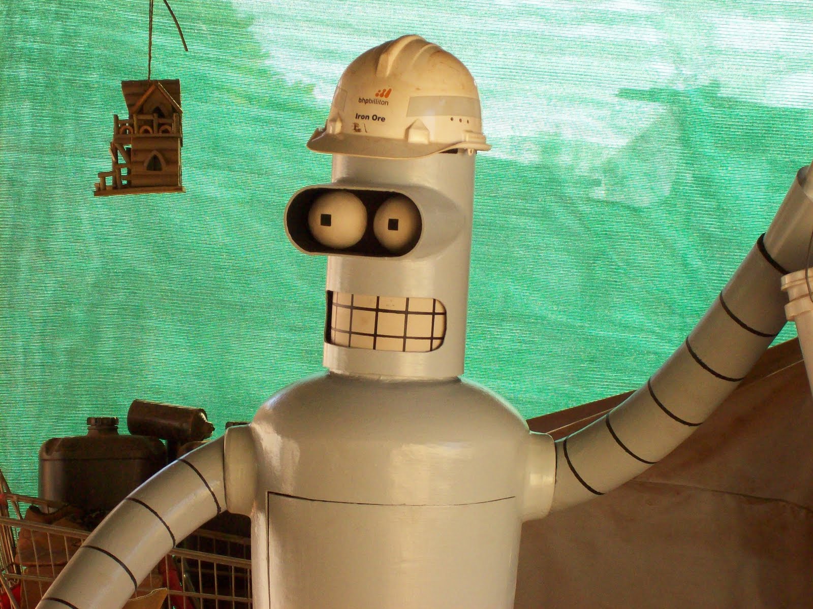
Bender is finally finished

What started with a "that's a funny look" at a 45kG (100lb) propane cylinder, with half a fire extinguisher perched on top (to keep the wasps out of the valve) has finally reached completion.

I was originally inspired by the bender brewing project at asciimation.co.nz.. but figured that my Bender would have to be metal. Since I didn't have any "40%iron, 40%titanium,etc,etc" alloys, I used the propane cylinder, old 9Kg (20lb) DCP extinguishers, pipe, and other bits and pieces to create this:

He stands 1600mm (5' 4") tall to the top of his antenna, and weighs 50Kg (110lb). His head rotates, the expression is changeable, and his arms can be moved at the shoulder joint, and the wrist.

I'll post a few more "finished" pics, and then go back and document some of the construction photos, techniques, and mistakes (I think my do-overs covered half the model)


I made two heads since I expected it to be difficult, and wanted a spare in case I screwed up badly. Thank fully most of my screwups weren't on the head, so I ended up with a spare head. Since I don't have a head in a jar for the photos, I used the spare head - after all we all know Bender enjoys his own company...
The spare head is currently being used for a bookshelf ornament, and is quite a conversation starter once people notice it.
Over the next month (work permitting), I'll finish the spare teeth panels, cigar, robotology symbol, and various eyelids to extend the range of emotions and looks he can have.

The construction photos will include some dimensions, tips, pointers, and oops.

Don't let the helmet fool you, he's not an employee of BHPBilliton Iron Ore - it's just one of the things I picked up off the side of the road when I collected the old fire extinguishers.