My Taig lathe has been residing on a sheet of 18mm MDF for the past 10 years. The sheet has a wooden drawer built in underneath it, and a clutch/ jackshaft system for speed control. I will put a photo up in this series of articles, but not yet, this post is more a "preview".
Basically the old base (lathe stand) works, but it has limitations and problems. Some of the problems are the result of a certain removalist, some the result of bad design on my part, and most are simply the result of cutting corners due to cost constraints. - whatever the reason, it's time to make things better.
I'll do up a series of articles covering the design and build (mechanical and electrical) later, but for now here's some progress photos and a brief note of some features...
Lathe stand/ cabinet features:
full length/width drip tray
2 lockable equipment drawers under the drip tray with full extension
removable swarf tray
swarf gate in drip tray for dumping swarf
removable back board
4 switched GPO's (power points) with MCB
adjustable motor mount with belt unloader (clutch)
fold in carry handles
magnetic base with enough thickness for tapping holes if needed.
enough room to permit/ support my planned projects (backgear, change-wheels, taper turning attachment, indicator bases)
Motor controls:
24VDC 500W PWM VSD with reversing switch
16-20A over current protection
NVR (No Volts Release) circuit with additional e-stop at tail stock end
Just waiting on the postman to deliver a few parts and this job is finished. The VSD cabinet (LHS rectangular section) contains:
500W 24VDC PSU (courtesy surplus parts online)
6800uF capacitor from a Seimens VVVF (for smoothing)
125mm fan (with some trickery in the ducting) for forced cooling
PWM circuit (with heatsinking)
control switches (Start, Stop, Speed control, reversing switch)
IEC socket with filter
DIN mount rail containing -
16-20A SFKOL overload protection device
NHP Terasaki MCB for isolating all 240VAC circuits
Industry standard relay mount and relay for NVR circuit
The DIN mounted components are accessible through the front panel (for resetting, or fault finding)

Both drawers are accessed from the front, on ball bearing slides with full extension - no excuse to have things lost in the back of the drawer again.

The removable back board supports the electrical circuits, and a tray for storing things during work - a work light will be attached to this backboard as well.

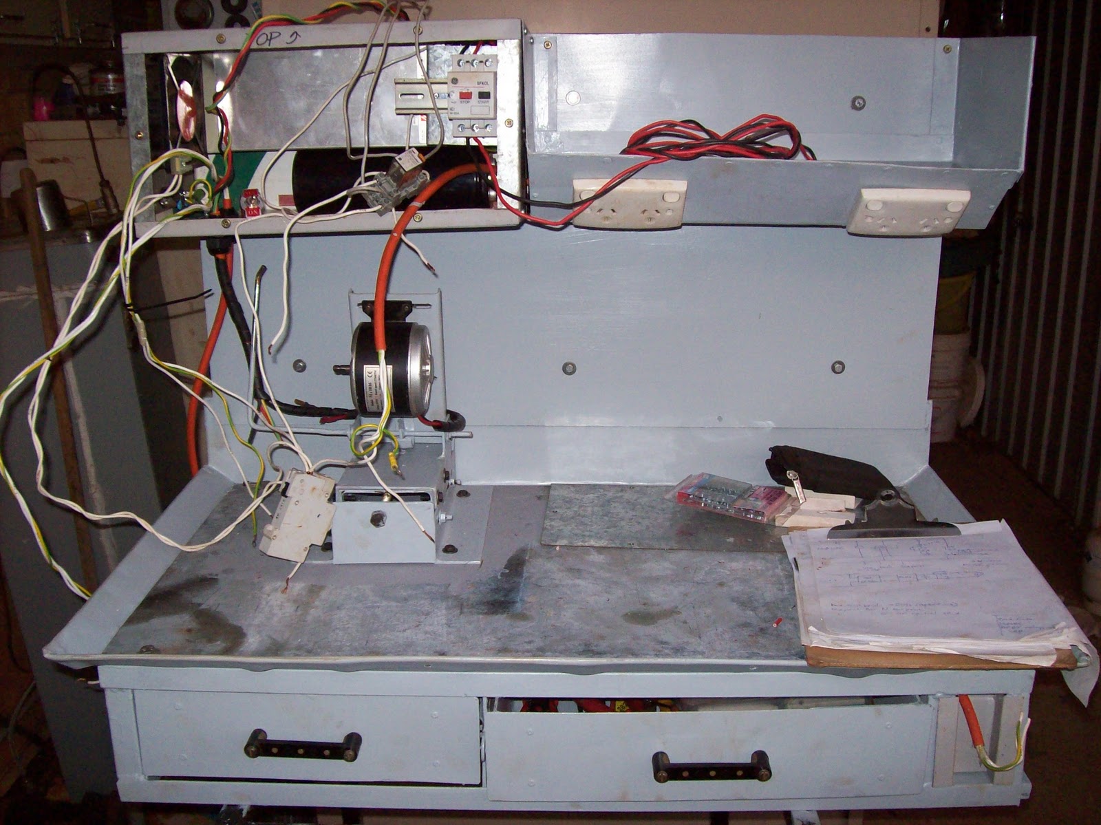
The range of travel in the "unloader" mechanism is shown here (the distance between the shaft and the vertical steel ruler - about 35mm (1.5")). The adjustable motor mount is shown midway through it's 100mm (4") of travel.

A photo from the tailstock end of the cabinet showing the tray mounted on the backboard - the rectangular holes visible in the slanting face are for the GPOs. The tray has a false floor and is sealed so the GPOs and cabling are protected. The GPOs were mounted in this manner (downwards sloping face) to provide easy access, but also make it impossible for swarf or coolant to fall into the outlet holes.
The materials used is basically salvaged sheet metal - some 4mm gal sheet for the load bearing areas, and sign-white (colourbond) for the rest.
The frame is a hotch potch of 25x25x3 angle, and some 25x25x1.6 square tubing.
All sheet metal bending (that worked - see future postings) was done using metal clamping with judicious use of hammers, wood blocks, and muttered cussin'
Most of the electrical parts are salvaged, however the power supply, and PWM section are purchased/ built - all other parts removed from salvaged equipment (even recycled some bus mounts from a switch board to make the drawer handles)
The techniques, design, and details will be covered once I get the main computer fixed (power outage cooked one of the bridges in the mobo - lost the O/S drive and a few other peripherals), and few other demands on me at this time
Next update will most likely be in two weeks time - the pictures are already taken, it's just time to type, format and upload.
