Monday, April 25, 2011

And now for something completely different - some quilts I made

Just for something a little different - much different than driving the lathe.

Everyone who knows me knows I have a myriad of interests, and will have a go at just about anything. I started sewing properly back in 1990, and have dabbled ever since. I've no plans to make a career out of it, but I've already saved a lot by doing alterations and repairs. Here is some photos of the two quilts I've made, or helped make.

Gift 2004 - Noah's ark quilt 1330 x 1560mm in size

Central panel hand quilted by my wife  - panel is one of the preprinted style available through the fabric stores.
Surrounding panels have a set of themes.
The two side sets (vertical set of 4 panels per side) are the land animals
The top set of panels (5 panels) are the animals of the air (birds and bugs)
The bottom set of panels (5 panels) are water animals.


The borders to the panels sets are made in the colours of the rainbow and orientated to form a circular pattern around the ark.
The corner panels also have a theme which commences in the low RH corner and is read in a clockwise direction.
Low Right Hand Corner - the rains commence and the waters start to rise
LLHC - the rains continue and the waters are significantly higher
ULHC - the dove brings back the olive sprig
URHC - the waters recede from off the face of the earth

All panels with the exception of the large central panel are made from machine based applique methods.
All fabric is poly cotton - pre-shrunk, and sewn with polyester threads.

The rain in the lower corner panels is over-sewn with a silver metallic thread for effect.

A sample of some panels are shown in the photographs


The panels were designed by downloading images from the internet of animals (I found colouring pages to be the best for size and line detail), or I simply drew the images myself. I then made the applique pieces, turned them, and sewed them in place to create the panel. Detail such as leaves, bubbles, etc were then added, and the panel completed.


The dove was particularly painful due to the colours of the rainbow.


I did a dragonfly, and used a chinzy tule to make it's wings so they retained their translucent effect... that was interesting to sew.


The quilt was made as a gift for my wife's best friend, and we both considered the effort we put into it time well spent for the recipient.

A quilt which I made for my beloved wife...
2006 - "Friends put a Bounce in your Heart" Winnie the pooh - 2100 x 2300mm in size

Started with a picture I downloaded from the internet which I blew up by clipping a sheet of builders plastic (orange translucent sheeting) to an overhead projector screen, and then opening the picture in a PC connected to a data projector.
Then it was simply a case of tracing the projected image onto the plastic and using that drawing for my cutting pattern.


Fabric was standard polycotton - preshrunk, sewn with polyester threads.
Style was normal machine applique.
 At this stage the tracks of the bees and butterflies form the only quilting in the border panels.
The corner panels are each quilted with one letter of "POOH"


This quilt was made during a holiday where my wife left town to visit family, and I built my furnace - My better half was gone for about 8 days, and I would get up each day and work on the furnace from 7am until 2pm, then clean up and work on the quilt from 2pm until 11 pm. I think I threw in a couple of full days 7am-11pm) as well just to ensure this was done before she returned. It then sat in storage for a few months until it was given to her for a Christmas gift.


There is a panel stitched into the back with the title and dates of the quilt.

Equipment:
I have 2 sewing machines, and one overlocker - All I'm missing now is a table tennis table so I have a large foldup surface for laying out patterns and pinnings. Currently I use old doors on saw horses.
The sewing machines are nothing fancy - an old Elna air electronic I purchased secondhand, and a cheap Toyota which we bought when the Elna was looking like it was struggling repairing heavy fabric clothes (denims) - both machines have functioned flawlessly as long as we look after them.

I don't make quilts often - too much on "the list" as it is, but I'm often sewing at least once every month or two doing clothing repairs, or making some little doo-dad. Two weeks ago I made some ID card holders since the one I use at work fell apart and I blamed it on the poor design... let's see if my new design lasts longer than 3 months, then I can skite about it. My multimeter case worked well and has held up for quite a while now without concern.


This is how the kitchen table looked whilst I was making the panels for the Noah's ark quilt... another reason why I don't make quilts too often.


Many many thanks to those people who have taught me various sewing tricks over the years... Mostly Lyn for first teaching me how to use a sewing machine, then Rosemary for first teaching me how to use an overlocker, and Myjalessa for all the fancy tricks. I know I've missed others, but those three certainly started me off with this.

Taig lathe cabinet -control panel and switches

To conclude the discussion about the construction of the lathe cabinet, I'll now cover the switches, and finer points of the control panel

In my day job (which seems to cover days, nights, weekends, and other times as well... but that's another story) I am quite familiar with industrial emergency switches - aka E-Stops, or "Lock off stops" (LOS)
Industrial E-stops tend to have replaceable contact blocks which bolt to the back of the switch mechanism, and these contact blocks can be double sided, stack-able, and able to be used in a variety of configurations to suit the control need.
I have one or two of these switches which I've salvaged from discarded equipment, but the contact blocks add at least 40mm (1 1/2") of depth behind the faceplate - unsuitable given the space constraints at the tail stock.


Figure 1 - Two N/C switches with perspex circles glued on

Since I only had 18mm (3/4") behind the switch at the tail-stock, I decided to build my own e-stop switch until a commercial alternative presents itself. I purchased a number of N/C (Normally Closed) momentary push-button switches from one of the e-bay stores (Virtual village from memory) to use as e-stops.
I also purchased some N/O (Normally Open) momentary push-button switches as well... for some reason the N/C switches were only available in Yellow, and the N/C in Red - no matter.

I then cut out some suitable sized circles of perspex (Hole-saw with the pilot drill removed - whole job done by clamping in a drill press) and glued the circles on the button face using a cyano-acrylate based glue (Loctite Prism, or some other form of "super glue" - aka "crazy glue")


Figure 2 - N/O switch with smaller perspex circle glued on, next to bored out PET bottle cap


The two e-stops were then painted red using a sheet of paper glued over the perspex, and paint sprayed onto that. The paper makes the perspex opaque, and helps it take the paint better.

A similar method was used to make the button on the N/O switch slightly larger, and painted green.

The N/O button was to become the "Start" button, and as such I felt should be shrouded to prevent accidental activation. I could have made a nice professional shroud using pipe with an end cap soldered in and bored out, or I could simply grab a lid from a PET soft-drink bottle and bore it out to match the switch body.


Figure 3 - Test fit of "Start" button in shroud - using tail-stock mini-panel for support.


The panel was marked out and drilled for all switches prior to painting, and the back was marked up to make wiring easier.

The PWM circuit (commercial kit from Oatley electronics - Kit K252 ) was grafted on to a surplus Pentium heat-sink, which was then screwed to the top inner surface of the control panel so the fan blew directly on it. The on-board potentiometer was replaced with a wired external unit which is accessible as the speed control knob on the control panel. I had a few hiccups with the kit, but not as a result of any problem of Oatley's... All resolved now, but issues included one terminal block cracking when tightened up, and a dodgy soldering job on one oscillator pin.


Figure 4 - Back of control panel with PWM circuit assembly resting on it

I used some of my salvaged spiral wrap for the cabling - turned out to be a disaster since the wrap was so old the plastic was brittle. I had a chat with Wayne at Rexel and bought some more.. cheap chinese stuff instead of the the Cabac brand we use at work, but certainly much cheaper... and it seems OK for my use.


Figure 5 - Control panel front view prior to painting or labelling.

The cabling of the control panel was covered in my previous post and will not be repeated.
The control panel was simply painted "Bender grey" along with all the panel work and a label was made up.
The label was made from creating the text and dial markings, warnings etc  in Paint, and then assembling them on a page and printing it out. I then cut the paper up, and rearranged them to match a tracing already done from the finished panel. Securing screws, holes for breakers, relays, controls etc were marked in and the text placed around them. Once completed, the finished sheet was then placed through a colour photocopier and trimmed for effect. A pass through a laminator and re-trimmed and it was ready to be glued to the control panel. Peter Homman described a similar method for the prototyping of control panels for products, including membrane switches - it's a good idea I was grateful to be able to learn from.


Figure 6 - completed control panel with paint and labelling


A quick few notes:
  • I won't be adding anything more to this Taig lathe cabinet article series unless someone needs clarification on something... use the "contact page" to send through any questions.
  • I don't plan on offering any drawings or plans.. I can take a few more photos, but that'll be only if requested.
  • If you're in Australia... look at Oatley for cheap kits and other interesting bits and pieces. The motor currently fitted to this lathe is one of their 300W scooter motors. Since there isn't a cheap source of treadmill motors in oz (similar to the big surplus stores in USA) this is a good alternative. I've bought from Oatley over the years and found their prices and range reasonably good for a number of products.

Lastly... what would I do differently if I repeated this project?
  • Use a finger brake for the panel work for a neater finish
  • Make the swarf gate bigger, and the swarf container smaller (so an industrial E-stop with contact block can fit)
  • Use more flexible cable for the 20A DC wiring
  • Add a separate circuit breaker to  allow the motor drive (PSU, and PWM, etc) and the fan to be operated separate from the supply to the GPOs
In the words of Porky Pig, "That's all folks"... next post will be back on one of the many other projects I'm trying to get off my "to do list"

Tuesday, April 19, 2011

Taig lathe cabinet - schematic and cabling

I started out designing the cabinet by deciding what I wanted (features list).
I wanted:
a) - drawers accessible from the front
b) - shelf above main deck for commonly used things
c) - a deck to support the lathe, with enough room for accessories
d) - the deck needed to be thick enough for drilling and tapping into
e) - the deck needed to be magnetic (for DTI bases)
f) - the deck needed to have a raised edge so things couldn't fall off it
g) - preferably no "traps" for swarf to build up in
h) - a way to easily remove swarf
i) - motor mount which permitted unloading of belt
j) - accessible power points
k) - variable speed motor
l) - reversing motor
m) - task lighting
n) - controls accessible without reaching through rotating parts
o) - cabinet wired as an "appliance"


Points J to O are basically electrical in nature and influenced the electrical design.
The electrical design was done with a sketched up line drawing based on the salvaged parts I had (from some scrapped switching machines)


Figure 1 - Hand drawn schematic of circuit

Whilst building the cabinet, I used a hand drawn schematic, but then once completed, I drew it up properly (Paint then exported to jpg) for the "point to point" testing.


Figure 2 - Schematic done to a more professional standard

The variable speed motor was accomplished with the use of a Pulse Width Modulated (PWM) controller, with a large (6800uF electro) capacitor added for smoothing - subsequent discussion on aus.electronics demonstrated that this smoothing cap should not be added, so it was subsequently removed. I added a 20A DPDT toggle switch for accomplishing the reversing function.
The mains voltage design started with a IEC socket (with line filter) which is switched through a 10A MCB (miniature circuit breaker). The circuit supplies a pair of double GPOs, and a fan which pulls air into the control cabinet. The supply to the PSU is controlled through a 10A DPDT relay which uses latching circuitry on one set of contacts to  hold the supply on to the PSU, dropping it when either "E-Stop" button is pressed. The relay pulls in if the start button is pressed, but loss of supply will release it, and restoration of supply will not automatically re-close it without another button press. This supplies the No Volt Release (NVR) functionality I wanted for safety.

Supply from the PSU is fed through a SFKOL (GE motor start over current protection device) and to the PWM speed control. The SFKOL protects the PSU from a short in the motor, cabling, or PWM circuit.


Figure 3 - Wiring commencement


Figure 4 - Wiring continued

All 240VAC wiring was done with 2.5mm2 cabling, and all 24VDC wiring done with 4mm2 cabling. I tried to maintain the wiring code relevant to Oz with respect to colours of cables, and marking of earth, etc.
The majority of cabling is contained within the control cabinet, but there is some cabling which is outside the cabinet. The motor cable, and base "E-stop" circuit are passed through the floor of the control cabinet using cable glands in a non-ferrous gland plate. Both cables have an Earth core, although the motor cable earth is not connected to anything at the motor.

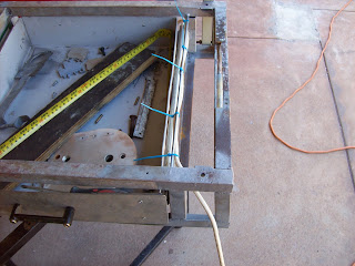
The E-stop cable has a protected connection on the rear of the backboard where connection can be broken for service. The cable to the RHS base E-stop (tail stock E-stop) is routed inside the tube frame for protection, and a 5mm (3/16") thick support rod was welded into the frame to support the cable so it couldn't foul against the drawers, or the swarf gate. The support rod is shown with a light gauge test cable. The heavier (orange sheathed) cable is held in place with the support rod using cable ties (aka zip ties).


Figure 5 - Tailstock cable support rod test

The back of the tail stock E-stop is shielded by a sheet metal cover, which terminates the Earth core. Bonding of this Earth to the base frame is accomplished by the face mounting screws, and another bonded cable.

The entire lathe cabinet is technically an appliance, and as such was tested for Earth Leakage, insulation resistance, etc prior to powering on. All tests passed.

Still to be described - the panel controls and constructing the switches.

Tuesday, April 12, 2011

Taig lathe cabinet - control panel and top tray

So far we've designed this cabinet, planned out it's size and requirements, then tweaked it as we went into construction. All that's left now is to build and fit the panels and tray which are mounted on the back board.

The backboard contains two parts - interconnected but with separate purposes.
a - the control panel which contains all the electrical circuitry for controlling the lathe including protection, speed and direction control. The control panel also contains the breaker for the GPOs (General Purpose Outlets - aka "power points")
b - A tray for holding items used often, or needing to be up out of the way.


Figure 1 - Two parts of the top tray

The top tray was designed as a simple tray, with a false bottom which contained some GPOs. The front face of the tray was angled so the GPOs pointed downwards to prevent ingress of swarf, or coolant. I could have mounted them on the bottom face of the tray, but prefer the idea of being able to see the state of the switches at a glance.
The tray was simply folded up out of sign-white sheet metal in two pieces - the tray proper, and the supporting structure.
Holes were cut into the front face for the GPOs, and an access hole was cut in the LHS wall for cable entry.
The two halves were then riveted together, and sealed with silicone sealant to prevent anything from the top tray leaking into the false floor.


Figure 2 - Top tray assembled


Figure 3 - Top tray bolted to backboard - view from RHS.

The control panel section is a simple box. The top, rear and bottom faces are all folded from the same piece of metal forming a "U" shape. Flangles are folded inwards to form faces for the ends and front to be screwed on.
Each end piece is a separate sheet with the LHS containing a cutout to match the cable entry hole in the tray. The RHS sheet has a variety of holes cut in it for ventilation and power entry. Both side sheets have a bent section to form the side flanges for securing the front sheet.
Heavier gauge sheet metal was used for the side and front sheets to provide strength to the structure, and to support the control switches.


Figure 4 - front view of control panel showing internal flanges

I determined the size of the control box by lumping all the planned components into a pile, and then estimating it's volume. A considerable factor for cooling, wiring, and access was then added and the resulting dimensions then used.
Once built, the components were thrown into the box to test the layout and volume.


Figure 5 - Volume test of finished control box

A drawing of the box and it's airflow is shown below. The issue of the heat the 500W PSU generated was a concern, so I tried to design effective airflow into the cabinet. The PSU has  a small fan inside it, and it blows hot air out one end... to make this more efficient, I folded up a small shroud to extend the fan end of the PSU to the LHS side wall of the control box, and cut a matching hole in the sidewall. A larger fan (surplus from when I upgraded my welder) was installed in the same sidewall - so cold air is sucked in, circulated through the control box and expelled through the PSU.

Figure 6 - sketch of air-flow and major components in control box

The front panel of the control box has been bolted on for the next photo. The front face is a simple sheet of galvanised sheet-metal.


Figure 7 - Plain front face of control box

Some paint, and then a handmade label, assorted holes, controls and an indicator lamp and this is how the control panel turned out...

Figure 8 - Finished control panel

The label was made using techniques attributed to Peter Homann  along with a myriad of minor tricks I picked up over the years. The warning labels cover the real risks of the lathe cabinet, and operating the lathe including: electrical, rotating parts, read instructions, wear PPE (Personal Protective Equipment.. eg safety glasses) and the most important of all... I copied and modified the logo from Hack-a-day with the advice to "not let warnings put you off being creative, or learning" since I believe too many in today's society become too scared of warnings to actually try something new.

What else about the control box? There is an aluminium gland plate in the bottom face of the box for the passage of  cabling to the motor and to the E-stop at the tail-stock.

The entire cabinet was painted with "Bender grey" paint - the darker of the two colours used to paint up Bender. The colour is nice, and I have over 5L ( about 6 pints) of paint left from painting Bender so I'll be painting a few things with it over the next few years.

The only topics left to describe with this project is the electrical systems including:
Schematics, wiring, switch construction, and controls. I daresay those topics will be covered in about 2 more articles, and then that will be it for the lathe cabinet unless there are questions.

Monday, April 11, 2011

taig lathe cabinet - drawers, slides and lock

On a roll here - hopefully the 'phone won't ring...

Drawers for the lathe cabinet.

A few design criteria I specified;
a - accessible from the front of the cabinet - previous stand was from the RHS (under tailstock) - never used because it required too large of a footprint on the workbench
b - no "un -viewable" space - the drawers had to be able to be viewed in their entirety.. to often the tool I need is found hiding in the very back of the drawer
c - drawers needed to be big enough to be useful, but small enough to be hard to overload
d - preferably lockable - more for controlling little fingers rather than theft.

To the "bin of useful junk"... and I returned with 2 pairs of drawer slides I had previously salvaged from some BIG photocopiers. These slides were used to house internal mechanisms (or was it 2000 sheet paper feeders.. I can't remember) so they're made tough, and best of all they extend out to 2.5 times their length.


Figure 1 - Salvaged drawer slides

When I built the base frame, I included some flat rails for bolting drawer slides in place. I had pre-drilled them to match the slides and simply welded them inside the frame. The centre rail was effectively double-sided since it was designed to hold a rail on each side, plus I made it longer to provide a tongue for a locking mechanism.


Figure 2 - Drawer slides fitted to base frame rails

The drawers were then drawn up on the sheet metal with a width to match the inside width of the drawer opening - drawer slide to drawer slide, depth, and height, to match the base frame - with suitable reduction for clearance.

The drawers were cut and folded using the previously described methods (clamped between tubing and angle-iron, bent over with bits of wood, and metal flatters)


Figure 3 - Drawers made and fitted to slides


After the mistakes were corrected, the drawers were shimmed up to the correct height for clearance, and holes drilled for the drawer slides. Bolts inserted, nuts tightened and all done.

The next step was to make some fascia sheets for the front of the drawers so the gaps around the sides for the drawers slides wasn't as obvious.. measure, drill, and pop rivet on.

The handles for the drawers are actually bus insulators from a switchboard I scrapped. A friend needed the breakers, and I disposed of the rest. The insulators were trimmed with the grinder, and then screwed in place to form the handles.


Figure 4- Drawer extended out to show the full drawer contents


As mentioned previously, the central slide rail was made extra long so a tongue protruded. This tongue was cross-drilled and a matching plate with slot was made from 4mm sheet. Locking the drawers is as simple as closing them both, then placing the plate over the tongue and slipping a lock on - illustrated here with a bolt.


Figure 5 - Demonstration of locked drawers

Writing this article doesn't do justice to these headaches these drawers caused... It's easy to blame my tools, but every one of the problems I had with these drawers actually highlighted something I'd read about, but luckily avoided thus far in the project.... metal stretch

If you're going to use the same methods I did for bending metal - clamping and hammering, be aware that the metal will stretch as you work it. I found the sheet metal stretched by about 4% over the length based on hammering in 4 bends... that doesn't sound too bad until you're trying to hold a dimension to within 2mm (about 1/16") so the drawer slides aren't tensioned in use.
The answer to the issue - test bends on scrap first, and clamp up tight to avoid shifting... the clamping is why I'd love to build a brake, but even then I'd still do test bends for high tolerance work.

Resulting drawer sizes...290W x 100H x 450D  and 375W x 100H x 450D (11.5" or 15" x 4"H x 18"D)


NB - A note about scrapping photocopiers... The local photocopy guy gets paid $50 for each defunct/ old copier and they get shipped to India for refurbishment... For $50 I can bring home a photocopier which is nearly the size of my 6' x 4' trailer and salvage many heavy duty slides, at least 4 NEMA 27 or 34 Stepper motors (and several smaller ones), a few PSUs, shafting, bushes, pulleys, mirrors, etc. It takes about 6 hours to tear one down to the last nut and bolt if you use a cordless driver, but you get a treasure trove of useful bits - hence why the Indians want them. A bonus, you get to learn about how they are built, the engineering and tricks in their assembly and design.

Next installment.. most likely the top tray and control panel.. that will wrap up the mechanical construction.

Taig lathe cabinet - swarf gate and dump

The reason for designing this cabinet with a drip tray with raised edges was due to the problems I used to have with things rolling off the flat board which was the prior base. Raised edges make it impossible to have things fall off, but make it harder to sweep swarf out.


Figure 1 - Swarf container on base board

Due to the loss of 100mm (4") of drawer width due to the  tail-stock end E-stop, I had a "space" I figured I could fill with a container to catch swarf. I had toyed with making this tray for holding things like chucks, but the inspiration regarding a swarf dump made the most sense.

The angle iron base meant I could make the tray sit upon a piece of board which could use the angle iron as a track to retain it. The container was folded up as per the panel beating page, and then screwed to the board.


Figure 2 - Swarf container "in place", simply lift the handle up to remove the container

With the container built, the gate to dump the swarf needed to be made. A track was made using a pair of lap joints on each side of the gate piece.

The swarf gate was made from an old discarded lifting lug which already had a 45mm (1 3/4") hole in it, and simply had a piece of strap welded to it so the gate was accessible from the tail-stock side of the drip tray.


Figure 3 - Swarf gate resting in LHS track

The lap joint used to retain the gate was made two ways... the RHS one was simply a piece cut from the angle iron which supports the base sheet, whereas the LHS one was made of two pieces of 4mm scrap cut and welded together.
Both lap joints are tensioned by means of small bolts which pass through the base sheet, and drip tray and thread into the lap joint rails.


Figure 4 - Swarf gate half open

To demonstrate the effectiveness of the gate - the nuts are some 8mm nuts which have seen better days


Figure 5 - Swarf resting on closed gate


Figure 6 - Gate dropped into container below when gate opened


Figure 7 - Opening at top of swarf gate less than 45mm

The holes in the base sheet and drip tray were cut and filed so they were deliberately smaller than the gate opening - this prevents material hanging up in the gate mechanism.

Next installment - drawers (slides, lock, and construction)

Personal notes:
Still learning how to make this new O/S work, but at least I can start catching up on these articles
Took some time over the weekend to watch sessions from General Conference - very rewarding and inspiring.

Until next time....

Sunday, April 10, 2011

Taig lathe cabinet - drip trays and panel beating

This article covers the construction of the drip tray (first and second attempt) and touches on the panel beating methods I used

As mentioned in the article regarding the frame, the objective of the lathe base was to have a substantial piece of metal which was thick enough to support drilled and tapped holes, magnetic (for use of mag-based tool stands), and to help dampen noise. Thinking I could do this by building a drip tray out of 4mm steel, I made a tray by scoring and cutting the sheet, and then bending and welding it up.


Figure 1 - pieces of 4mm sheet scored and bent


Figure 2 - 4mm sheet welded up to form drip-tray #1


Figure 3 - resulting drip tray from 4mm sheet - distorted and not flat

BIG PROBLEM - the resulting tray buckled during welding and would not provide a flat base. no amount of cussin' or hammering would fix that. - on to Plan B.

Plan B was to use a thinner metal to make the drip tray, and then use a separate sheet to form the solid base floor. The frame was built to support this design, and the base sheet cut and fitted. From that sheet, all other measurements for the drip tray were derived.

The drip tray is made from colourbond "sign-white" - a thin sheet metal coated to prevent rust (some kind of zinc-aluminium coating) and coated in a bonded white paint - it's used by sign writers to make shop signs - hence the name. The other side is a pale grey colour, and this became the visible side since it was easier than trying to remove the old vinyl lettering from the white side.

My source of sign-white is a number of discarded signs which I obtained soon after moving to this town. The frames for the signs quickly became stock for building a myriad of doors, shelves, etc, and the panels have become door skins, guards, and a number of other tasks. This lathe drip tray commenced the use of the last full sheet.


Figure 4 - commencing the folding of the drip tray (#2) - forming the wired edge

Since I don't have a pan or finger brake (yet another project yet to start) , I improvised using tube and angle iron clamped together (often the tube was one side of an old table frame). The "mallet" was a piece of pine timber, and a piece of 2"x 1/4" flat bar was used as a flatter to help crisp up the edges. I formed up a wire edge for the edges of the tray where hands would touch by folding the sheetmetal around a strip of 3mm x 25mm (1/8" x 1") strip and hammering it flat with a mini sledge hammer.. after everything was folded up, this gap was then closed up to complete the wired edge.


Figure 5 - completed drip tray with wired edges for safety

This method of folding was used throughout this entire project - drip tray, drawers, trays, control cabinet - all fashioned with bits of tube or angle iron, 3 clamps, a piece of timber (with or without a flatter), and a pair of ear muffs to drown out the noise.


Figure 6 - completed drip tray and back board


Figure 7 - Rear view of back board showing overlap

Next article will cover the swarf gate and accompanying swarf drawer.
Still to come:
Drawers, electrical circuit, "home made" switches, control panel

Friday, April 8, 2011

Taig Lathe cabinet - base frame

The frame of the lathe stand

The frame was built based a size calculated to permit the Taig lathe to be mounted with enough room to allow the mounting of a motor, space for changewheels, backgearing, control space for the leadscrew control, and any accessories I planned including a taper turning attachment and profile copier.
 

Figure 1- Base frame with headstock reinforcing

The overall baseplate dimensions became 500 x 850mm (20 x 33.5"). The baseplate became the core of the design with a sheetmetal tray built to sit under it with a lip coming up from the front and sides, and an extended lip coming up at the back making a swarf tray capable of containing swarf or coolant.


Figure 2 - Base frame with drip tray and top sheet

The frame was welded up from 20x20mm (3/4 x 3/4") angle iron, or tubing from the scrap pile.


Figure 3 - Base frame with backboard frame attached

The Taig lathe is a cantilever bed lathe with a foot under the headstock. To provide a strong stable mount for the lathe I welded a piece of 4mm (5/32") into the base. (shown in Figure 4) This means the lathe is mounted to 8mm (4+4mm) of steel, whereas the rest of base will have a thickness of only 4mm. I deemed 4mm as thick enough for magnetic bases, or drilling and tapping into, whereas I felt it prudent to have it thicker under the lathe foot, and for mounting the motor assembly.


Figure 4 -Base frame from rear, showing angle iron brackets for back board, and reinforcing sheet at headstock

The backboard for the lathe stand adds 560mm (22") to the height of the stand and runs the full width of 910mm (36"). The backboard is attached to the baseframe by some bolts mating the board to some angle iron brackets.(refer Figure 4)

The frame contains room underneath the baseplate assembly for drawers - the height of which is 100mm (4"). The drawer widths are governed by the spacing of the stiffeners added to support the plate under the lathe foot, and a small offset at the tailstock end to support the E-stop. The space behind the E-stop is used to house a "swarf drawer".


Figure 5 - Bare frame with drip tray and top sheet removed, backboard frame attached.


The frame has 2 fold-away handles attached for moving the lathe - these are located at each end of the base.


Figure 6 - The fold away handle at the tailstock end of the base frame

The backboard was clad with a sheet of polycarbonate approximately 6mm (1/4") thick (a salvaged shop display shelf when the local postoffice was renovated), and a piece of colourbond "signwhite" from a salvaged shop sign. The sheet of polycarbonate served 2 purposes:
a - the additional thickness stood the sheet of colourbond away from the frame at the bottom edge permitting the lip of the base drip tray to slide behind it - preserving the sealing of the tray assembly, and
b - the additional thickness added stiffness and "meat" to the backboard providing substance for screws to engage with, and to dampen any movement in the colourbond sheet.


Figure 7 - clad backboard - rear view.

A few other features are in the frame, but those will be elaborated upon during the articles describing what they support.
Overall dimensions - 710 (H) x 550 (D) x 910 (W)  = 28" x 22" x 36"