Well it's been a while since I posted - lots happening.
Long story short, I'm in the middle of moving house due to a change in my employment conditions. This means for the past 4 weeks I've been working shifts, and had the house in boxes... and those boxes won't open for another few weeks, and I'll continue on shift even after that.
Longer term this means a shift in my projects whilst I shake down the house, and get the shed/s up. For quite some time, the projects will be limited to small things done in the field desk, and a lot of home renovation/ repair work.
Whilst I'm in the shift situation, I will be flying a lot, and getting very little done except on my off swing - then it's flat out getting work done at home.
I don't want to be doing FIFO (Fly In, Fly Out) and shift long term, this was a decision accepted based on the conditions under which I currently work, my scope for promotion, and other factors. I am applying for other work within the company since it is a great company to work for, and I don't really want to leave it if at all possible.
Current challenges:
trying to keep losing weight whilst surrounded by "camp food"
trying to remain busy developing my skills in Control Systems, Electrical Engineering, and Managemnt (Personelle and Project)
trying to keep busy with my hobbies and interests
trying to not let the distance and seperation from my family cause issues or concerns
Next challenges:
Overcome whatever obstacles prevent me from obtaining my next job - the one which allows me to spend time with my family, and still meet my financial commitments.
Underfloor ventilation in a building built in the 1950's (or was it 1850's?)
adjustments to various sewerage/septic systems
repairs alterations to fencing - boundary and pool
repairs and alterations to existing "shed"
minor extensions and modifications to house
construction of shed/studio on site to suit my needs - now and future
construction of granny flat (ancillary accomodation) on site
That's it for now - Once everything is unpacked, and settled down, I'll update this with some archived projects, and some of the "home owner" projects as they arise. Hopefully I'll be in a position to accept a new role, and spend more time with my family, and less time away from them.
Monday, November 14, 2011
Saturday, September 17, 2011
Construction Photos for Serial Cable kit - Mk3/4
The serial cable kit was formally released at work last week - the usage instruction manual was completed, and the construction manual as well. Confirmed cost came in at $48.87 per kit if 20 were made, $97 to make a single using company approved vendors and their MOQs for certain parts - If Ebay was used, the price per single kit still sits around $40. Either way you look at it, it is a dramatic reduction in price compared to the Mk2 kits I made back in 2008 - they came in at $400 per kit for the same functionality as the Mk3/4 Kits.
In the meanwhile here are a few photos taken during construction, and a couple of snapshots of the finished kit, and construction manual.
The baseboard is a small segment of breadboard anchored to a baseboard which incorporates the breadboard, the serial cable terminations, cable anchors, and module "ejection mechanism"
Everything in this kit was designed to minimise costs, and as such salvaged materials were used wherever possible - including salvaged screen-door extrusion for the anchor plates -the construction manual has drawings of all parts to be constructed, and alternate dimensions/ drawings if the extrusion was substituted with pieces made from simple sheet metal.
The "modules" are simply modified IC sockets, which are later labelled and "potted" for protection and resilience.
The serial cable is modified to suit the cable kits requirements. All construction for the prototype kits was made using tooling and equipment in my field desk - including the third-hand, modified pliers, solder pens, etc
Compact/ resilient storage of the kit and components was one of the deliverables I placed in the kit design. I accomplished this by modifying a commercially available storage box, and then constructing stack-able compartments which slid inside the outer case.
The user manual was deliberately formatted so when printed it could be trimmed to fit in a designated space in the the container - the finished manual measures 245 x 185mm (9 5/8 x 7 1/4") and is around 25 pages thick (printed in duplex, but with 6 pages of blank paper for notepaper)
I will have to "de-crest" the manual/s if they were published here since they reference work, and the department I work in - since they were the target audience of the design.
I've blanked out the company/ section details, and my address information on the thumb-drive label - hence the white blotches
The construction manual contains a number of progress photos, drawings, tips and alternate materials discussions. I wrote the manual with second year electrical apprentices in mind - some familiarity with basic hand-skills, interpretation of drawings, and the sense to know what holes get changed if you change a countersunk screw from 3/16"-24 to 4mm. The manual printed out to 29 pages of duplex A4.
In the meanwhile here are a few photos taken during construction, and a couple of snapshots of the finished kit, and construction manual.
 |
| Photo 1 - breadboard cut to form baseboard |
 |
| Photo 2 - Baseboard and anchor plates - under construction |
The "modules" are simply modified IC sockets, which are later labelled and "potted" for protection and resilience.
 |
| Photo 3 - "Modules" under construction |
 |
| Photo 4 - Serial cables being modified to suit kit |
 |
| Photo 5 - Completed modules in stacked storage compartment |
I will have to "de-crest" the manual/s if they were published here since they reference work, and the department I work in - since they were the target audience of the design.
I've blanked out the company/ section details, and my address information on the thumb-drive label - hence the white blotches
 |
| Photo 6 - Completed kit with instruction manual in lid |
 |
| Photo 7 - Sample page from construction manual |
As mentioned, I'll have to de-crest the manuals before publishing them here - not a huge amount of work, but still anything which adds to my "TTD (Things to Do) list" is not overly welcome right now. If I get some time spare, I'll do it in the next week or so, and add them here: (links will reference google docs)
User Manual
Construction Manual
I'll post again when something is completed, progressing, or worth discussing.
Saturday, September 3, 2011
solder pens, electronic tooling, and catch up
I was at a course the other day and one of the whiteboard markers ("dry-erase" markers according to Dilbert) ran out - I intercepted it before it got tossed out to make another "solder pen" No-one at the course had heard of them, so here is a quick explanation and construction article.
When I first started in electronics I simply used solder held in my hands - quite mindful of the warnings regarding lead poisoning, and always washed my hands after working. I don't remember where or when, but somewhere I saw someone use an old de-soldering wick packet to hold small coil of solder (see picture) - this became my preferred soldering method for the next 10-15 years.
When I built the field desk, I set about duplicating my old faithful toolkit, and found I didn't have any spare de-soldering wick packets...hence I turned to the soldering pen idea. I can't claim credit for it's invention, it's been around for years in various guises from clear containers with the solder poking out, to references on aus.electronics to people filling chemy pen (permanent markers) cases with solder.
So how to make a solder pen - select an old marker which has run out of ink, and remove the nib (pliers simply pull it out) and then get the cap at the end out. Sometimes it's necessary to trim away about 10mm (3/8") of the outer case at the end to allow the end-cap to be removed.
Then measure the internal length of the casing, and select a screwdriver or other thin smooth rod as a mandrel.
Wind the solder around the mandrel to match the length of the length of the case internals leaving around 50mm (2") of solder free at the start - this starting piece will end up being the first of the solder to be used. once one layer has been wound to the correct length, carefully wind back over for a second layer, stopping about 2-3 turns shy of the beginning of the first layer. Keep winding back and forth adding layers neatly until the wound solder is a loose fit in the case.
Cut or break the solder at that point, and gently remove the screwdriver (I found gently rotating it made extraction easier). The bundle of solder will be quite flexible so care must be taken to not stretch or kink it.
Straighten the starting piece of solder, and centre it along the axis of the bundle, then feed it into the marker case so the starting piece protrudes where the nib used to be... this means the coils of solder will feed from the inside of the bundle, hopefully preventing tangles.
Replace the end cap, and you can fold the protruding solder over the nib holder and replace the original cap.
In use, simply remove the cap, tug an inch or so of solder out, and apply solder as required by holding the marker body. As the protruding solder is consumed, simply tug more out of the marker body as required.
I measured the weights of all my solder pens, and found they averaged 50gm (about 2 Oz) of solder in each one.
A bonus tip...
When I was at uni, I got on to a bulk purchase of quality electronics tools - cost us $120 to get excellent tooling - a fortune back then. When I duplicated my kit into the field desk, I wanted similar shape and quality tools, but did not want to spend too much money.
I purchased cheap pliers from the local KMart, and then using grinders, and files, reshaped them to suit my needs. In photo 6 you can see 2 pairs of pliers I've reshaped - the yellow handled pliers are just as good to use as the expensive ones in my old kit. The red ones are too small for use, but are handy for periodic use with the yellow pair for straightening or bending wire.
What else to talk about....
I finished the serial cable kits - Mk3 and Mk4 in total. Mounting boards, storage containers, etc. I've practically finished the user manual, and have only 2 sections left in the construction manual to finish... Mostly final edits in the sections, then renumbering the photos and illustrations. Still deciding if the documents should be published here or not, but I'll most likely add some of the construction photos at the minimum..
Various things happening at work... not much to talk about yet, but I daresay I'll have something to talk about soon.
When I first started in electronics I simply used solder held in my hands - quite mindful of the warnings regarding lead poisoning, and always washed my hands after working. I don't remember where or when, but somewhere I saw someone use an old de-soldering wick packet to hold small coil of solder (see picture) - this became my preferred soldering method for the next 10-15 years.
When I built the field desk, I set about duplicating my old faithful toolkit, and found I didn't have any spare de-soldering wick packets...hence I turned to the soldering pen idea. I can't claim credit for it's invention, it's been around for years in various guises from clear containers with the solder poking out, to references on aus.electronics to people filling chemy pen (permanent markers) cases with solder.
 |
| Photo 1 - Original "solder - holder" and de-soldering wick |
 |
| Photo 2 - dismantled marker pen |
Then measure the internal length of the casing, and select a screwdriver or other thin smooth rod as a mandrel.
Wind the solder around the mandrel to match the length of the length of the case internals leaving around 50mm (2") of solder free at the start - this starting piece will end up being the first of the solder to be used. once one layer has been wound to the correct length, carefully wind back over for a second layer, stopping about 2-3 turns shy of the beginning of the first layer. Keep winding back and forth adding layers neatly until the wound solder is a loose fit in the case.
 |
| Photo 3 - screwdrivers being tested for length |
Cut or break the solder at that point, and gently remove the screwdriver (I found gently rotating it made extraction easier). The bundle of solder will be quite flexible so care must be taken to not stretch or kink it.
 |
| Photo 4 - solder bundle completed |
Straighten the starting piece of solder, and centre it along the axis of the bundle, then feed it into the marker case so the starting piece protrudes where the nib used to be... this means the coils of solder will feed from the inside of the bundle, hopefully preventing tangles.
Replace the end cap, and you can fold the protruding solder over the nib holder and replace the original cap.
 |
| photo 5 - Solder test inserted into marker body |
In use, simply remove the cap, tug an inch or so of solder out, and apply solder as required by holding the marker body. As the protruding solder is consumed, simply tug more out of the marker body as required.
I measured the weights of all my solder pens, and found they averaged 50gm (about 2 Oz) of solder in each one.
 |
| Photo 6 - solder pens completed with other tools |
When I was at uni, I got on to a bulk purchase of quality electronics tools - cost us $120 to get excellent tooling - a fortune back then. When I duplicated my kit into the field desk, I wanted similar shape and quality tools, but did not want to spend too much money.
I purchased cheap pliers from the local KMart, and then using grinders, and files, reshaped them to suit my needs. In photo 6 you can see 2 pairs of pliers I've reshaped - the yellow handled pliers are just as good to use as the expensive ones in my old kit. The red ones are too small for use, but are handy for periodic use with the yellow pair for straightening or bending wire.
What else to talk about....
I finished the serial cable kits - Mk3 and Mk4 in total. Mounting boards, storage containers, etc. I've practically finished the user manual, and have only 2 sections left in the construction manual to finish... Mostly final edits in the sections, then renumbering the photos and illustrations. Still deciding if the documents should be published here or not, but I'll most likely add some of the construction photos at the minimum..
Various things happening at work... not much to talk about yet, but I daresay I'll have something to talk about soon.
Sunday, July 31, 2011
Serial Cable Kits - Mk1 to Mk4 - the answer for versatile industrial connection
Now for something a little different
In my day job, connecting a PC (laptop) to various industrial devices is fairly common. As is typical of these types of devices (VVVFs, Sensors, CPUs, etc) each manufacturer will require a different cable pin-out for their devices, (and some like Siemens require different cables for different models)
When I first started in my role, the "cable kit" comprised of a couple of cardboard boxes full of cables - each cable was around 1800mm (6') long, and sometimes labelled to say what it was used for.
I consider that the "Mark 1 cable kit" - large clumsy, difficult to use, and quite heavy.
I made up the "Serial Cable Kit" - this comprised a single full length DB9 straight through cable, and a number of "dongles" which were fitted to the end to change the internal wiring configuration. Each dongle was labelled, and an instruction book allowed the user to look up the device they intended connecting to, and the manual would tell them what cable and dongle combination to use - eg Siemens Masterdrive would require cable "C1" and Dongle "D2".
This system worked for a few years - it was well received by all who used it - a number of the kits were stolen, and other parts were added as new devices were added to the plant equipment.
Since I made this kit from home, I tried to keep the costs as low as possible (using double ended connectors proved cheaper than using 2 DB9 head shells with a short intermediate cable), the carry case was one from the local K-Mart (Think Wallmart) and modified.
The new kit was a considerable improvement over the original system, but after some time, and sick of fixing/ replacing missing parts, I decided a newer iteration was in order...
If the box of cables was "Mk 1", then the original "Serial Cable kit" would have to be "Mk 2"... Mark 3 would need to be smaller again, cheaper, lighter, and more versatile...
The "Mk 2" dongles were 2 DB connectors separated by a distance of around 40mm (1 3/4") with the cores between being short lengths of flexible cable.. I could accomplish the same effect using a piece of bread board (electronic prototyping board) and a number of pre-terminated jumper wires. That would significantly reduce the weight, cost, and increase the versatility infinitely. I bought some cheap breadboards off the internet and got one of my spare straight through DB9-DB9 cables. I cut the cable at the PC end, at around 400mm. In use the breadboard area would need to be close to the laptop so it was supported, not hanging off the front of a panel in a substation.
I belled out the pins and soldered the cores to a short length of header strip in order - pin 1 at the top, pin 9 at the bottom. This was repeated for the second length of the cable (around 1500mm (5') long.
The two header strips were inserted into the breadboard with pin 1 in row 1, and the same on the other side of the center strip. - This gives each pin of the serial cable 4 holes to connect cables into - the same for each pin on the outbound cable.
Using the diagrams in the Mk 2 instructions, I know I can rearrange the jumpers to make any combination of cable schematic, and I also know 4 holes per core is enough since the most any current dongle uses is 3 cores to one pin.
The shields from the two parts of the split cable are joined to the backing of the breadboard underneath - Once it passes all tests, the breadboard will be enclosed in a small metal tin to complete the shielding.
The Mark 3 version sounds great doesn't it?... meets all requirements, how could it be made any better? - it can be.
Mark 4 (or Mk IV if you prefer)
Currently the Mk 2 kit has 12 dongles in it - these are used to access over 20 different devices on site. Imagine the scenario where you are working on a fault - you need to talk to a VVVF drive, then talk to an ultrasonic sensor, then back to the drive, then to the PLC CPU... with the Mk 2 kit, you simply changed dongles as you moved from device to device... With the mark 3 you would be constantly changing the jumpers... if you're tired, distracted, you could too easily make a mistake - you could damage equipment, or at least waste time complicating your own fault-finding strategy. I needed a way to make the Mk 3 system as easy to use as the Mk 2...
The step to Mk4 was easy - simply use the existing breadboard to hold a "dongle" which had the jumper configuration in it. Make it removable, and make it "labelled". Immediately the concept of using a DIP IC socket sprang to mind. If I used a 18 pin DIP socket, that would give me 9 pins up one side, 9 up the other, and a small space in the middle to solder in the jumper configuration. The DIP socket has a notch for Pin 1 which can be used to ensure the correct orientation when inserting it, and I could pot in the jumpers to provide a space for a label.
NB: I chose machine pin DIP socket since the pins are stronger and round - making them better for the breadboard when compared to typical cheap DIP IC sockets.
I ordered a fistful of machine pin DIP 18 pin IC sockets from Futurelec (along with some other goodies) and started planning the next design. Once the sockets arrived, the first dongles were being made.
Since I don't have a Siemens VVVF at home, I cannot show photos of the system in use, but if possible I will get one from work.
In use the new kit will comprise of the Mk3 and Mk4 parts. The Mk3 cable and base forms the base kit, and 12 jumpers will be included for new or experimental equipment. The current manual will be re-written for the Mk4 "dongles" which will need to be renamed, and stored. This new kit has more versatility than the current kit, and is significantly cheaper to make up. Each "dongle" in the Mk 2 kit costs over $7 AUD, whereas each "dongle" in the Mk 4 kit costs $0.40 AUD. The new kit is much smaller, lighter to carry, and should be cheap enough to make as a "personal issue" tool - that last bit is handy to reduce theft and loss of parts.
I keep talking about "versatility" - it's the ability of the kit to handle making a new configuration out in the field - The Mk 1 kit had none, the cables were made "as -is", the Mk 2 kit had one spare unassembled dongle of each configuration (M-M, M-F, F-F) in the kit to permit making a new dongle, whereas the Mk3 (and Mk4)have the breadboard space and jumpers to create new configuration cables on the fly.
So the Mk 3 and Mk 4 work on the same principle of changing pin assignments, the difference between the Mk 3/4 and the Mk 2 is that it's done "inside" the cable, and reduces the amount of needed hardware.
There was one dongle which needed a special case... D12
All other dongles in the Mk 2 kit terminate with either a male or female DB9 connector - the Mk3 and Mk4 kit has a female connector at the end of the cable, and a miniature gender bender included for when a male connection is required... but dongle "d12" however terminates with a RJ11 connection - this is used for the HMI AnyBus equipment.
I had 2 options... option 1 was to reuse the existing "d12" dongle and simply have a "straight through" dongle for the breadboard... Option 2 is to have the 4 core cable for the RJ11 come off the "dongle" and leave the remaining 1500mm length of 9 core cable unterminated. I've made both, but look forward to testing option #2 since it makes for a more consistent approach.
Some statistics (estimated where shown *) - excludes Siemens Simocode Pro cable and USB-RS232 Adapter from all comparisons - based on cables/ configurations to perform tasks of Mk 2 kit.
Mk 1 kit - weighed 4000g*, volume 400x400x400mm* = 64L, cost ~$400-800 - No labels, no instructions, no versatility
Mk 2 Kit - weighed 1800g, volume 360x290x70mm = 7.3L, cost ~$250 - Labelled, instructions, limited versatility
Mk 3 Kit - Weighed 300g, volume 250x200x50 = 2.5L, cost ~$45 - No Labels, instructions, versatile
Mk 4 Kit - Weighed 350g, volume 250x200x50 = 2.5L, cost ~$50 - Labels, instructions, versatile
Labour? - all costs do NOT include assembly labour - I made the Mk 2 kits myself over the period of 2 weeks working 4 hours each night (7 kits) - I've made my own Mk 3 kit, and will complete the Mk 4 kit over the next week or so... what takes the longest is writing the instructions, and hand construction of the dongles. - you should allow between 15 and 30 mins per dongle based on intermediate hand skills.
What's not shown in any of the photos is the base plate for the Mk 3/ 4 set - I'm still trying to design and construct a "flipper" to permit easy extraction of the IC sockets - I was using an IC extractor in testing, but would prefer something "captive" so it can't be lost. In the meanwhile testing continues with another piece of breadboard for the noise immunity of the Mk3 and Mk 4 designs.
If you think this is a good idea and want to manufacture them - go for it - please give credit where due though... I do when I write the manuals.
In my day job, connecting a PC (laptop) to various industrial devices is fairly common. As is typical of these types of devices (VVVFs, Sensors, CPUs, etc) each manufacturer will require a different cable pin-out for their devices, (and some like Siemens require different cables for different models)
When I first started in my role, the "cable kit" comprised of a couple of cardboard boxes full of cables - each cable was around 1800mm (6') long, and sometimes labelled to say what it was used for.
I consider that the "Mark 1 cable kit" - large clumsy, difficult to use, and quite heavy.
I made up the "Serial Cable Kit" - this comprised a single full length DB9 straight through cable, and a number of "dongles" which were fitted to the end to change the internal wiring configuration. Each dongle was labelled, and an instruction book allowed the user to look up the device they intended connecting to, and the manual would tell them what cable and dongle combination to use - eg Siemens Masterdrive would require cable "C1" and Dongle "D2".
 |
| Photo 1 - Mk 2 Serial Cable kit in case |
This system worked for a few years - it was well received by all who used it - a number of the kits were stolen, and other parts were added as new devices were added to the plant equipment.
Since I made this kit from home, I tried to keep the costs as low as possible (using double ended connectors proved cheaper than using 2 DB9 head shells with a short intermediate cable), the carry case was one from the local K-Mart (Think Wallmart) and modified.
The new kit was a considerable improvement over the original system, but after some time, and sick of fixing/ replacing missing parts, I decided a newer iteration was in order...
 |
| Figure 2 - Mk 2 Cable kit concept drawing |
 |
| Photo 3 - Mk2 cable and dongle on relevant instruction page |
 |
| Photo 4 - Mk 2 Dongle with dongle schematic |
The two header strips were inserted into the breadboard with pin 1 in row 1, and the same on the other side of the center strip. - This gives each pin of the serial cable 4 holes to connect cables into - the same for each pin on the outbound cable.
Using the diagrams in the Mk 2 instructions, I know I can rearrange the jumpers to make any combination of cable schematic, and I also know 4 holes per core is enough since the most any current dongle uses is 3 cores to one pin.
 |
| Photo 5 - Mk 3 prototype configured as if Dongle 2 in place |
The Mark 3 version sounds great doesn't it?... meets all requirements, how could it be made any better? - it can be.
Mark 4 (or Mk IV if you prefer)
 |
| Photo 6 - Mk 4 "dongle" in place for Master drive communications |
The step to Mk4 was easy - simply use the existing breadboard to hold a "dongle" which had the jumper configuration in it. Make it removable, and make it "labelled". Immediately the concept of using a DIP IC socket sprang to mind. If I used a 18 pin DIP socket, that would give me 9 pins up one side, 9 up the other, and a small space in the middle to solder in the jumper configuration. The DIP socket has a notch for Pin 1 which can be used to ensure the correct orientation when inserting it, and I could pot in the jumpers to provide a space for a label.
NB: I chose machine pin DIP socket since the pins are stronger and round - making them better for the breadboard when compared to typical cheap DIP IC sockets.
I ordered a fistful of machine pin DIP 18 pin IC sockets from Futurelec (along with some other goodies) and started planning the next design. Once the sockets arrived, the first dongles were being made.
Since I don't have a Siemens VVVF at home, I cannot show photos of the system in use, but if possible I will get one from work.
In use the new kit will comprise of the Mk3 and Mk4 parts. The Mk3 cable and base forms the base kit, and 12 jumpers will be included for new or experimental equipment. The current manual will be re-written for the Mk4 "dongles" which will need to be renamed, and stored. This new kit has more versatility than the current kit, and is significantly cheaper to make up. Each "dongle" in the Mk 2 kit costs over $7 AUD, whereas each "dongle" in the Mk 4 kit costs $0.40 AUD. The new kit is much smaller, lighter to carry, and should be cheap enough to make as a "personal issue" tool - that last bit is handy to reduce theft and loss of parts.
I keep talking about "versatility" - it's the ability of the kit to handle making a new configuration out in the field - The Mk 1 kit had none, the cables were made "as -is", the Mk 2 kit had one spare unassembled dongle of each configuration (M-M, M-F, F-F) in the kit to permit making a new dongle, whereas the Mk3 (and Mk4)have the breadboard space and jumpers to create new configuration cables on the fly.
 |
| Photo 7 - Showing size comparison for Mk 2 dongle and Mk 4 dongle |
 |
| Figure 8 - Mk3 and Mk4 concept schematics |
All other dongles in the Mk 2 kit terminate with either a male or female DB9 connector - the Mk3 and Mk4 kit has a female connector at the end of the cable, and a miniature gender bender included for when a male connection is required... but dongle "d12" however terminates with a RJ11 connection - this is used for the HMI AnyBus equipment.
I had 2 options... option 1 was to reuse the existing "d12" dongle and simply have a "straight through" dongle for the breadboard... Option 2 is to have the 4 core cable for the RJ11 come off the "dongle" and leave the remaining 1500mm length of 9 core cable unterminated. I've made both, but look forward to testing option #2 since it makes for a more consistent approach.
 |
| Photo 9 - Mk 4 version of Dongle "d12" for 4 core RJ11 |
Mk 1 kit - weighed 4000g*, volume 400x400x400mm* = 64L, cost ~$400-800 - No labels, no instructions, no versatility
Mk 2 Kit - weighed 1800g, volume 360x290x70mm = 7.3L, cost ~$250 - Labelled, instructions, limited versatility
Mk 3 Kit - Weighed 300g, volume 250x200x50 = 2.5L, cost ~$45 - No Labels, instructions, versatile
Mk 4 Kit - Weighed 350g, volume 250x200x50 = 2.5L, cost ~$50 - Labels, instructions, versatile
Labour? - all costs do NOT include assembly labour - I made the Mk 2 kits myself over the period of 2 weeks working 4 hours each night (7 kits) - I've made my own Mk 3 kit, and will complete the Mk 4 kit over the next week or so... what takes the longest is writing the instructions, and hand construction of the dongles. - you should allow between 15 and 30 mins per dongle based on intermediate hand skills.
What's not shown in any of the photos is the base plate for the Mk 3/ 4 set - I'm still trying to design and construct a "flipper" to permit easy extraction of the IC sockets - I was using an IC extractor in testing, but would prefer something "captive" so it can't be lost. In the meanwhile testing continues with another piece of breadboard for the noise immunity of the Mk3 and Mk 4 designs.
If you think this is a good idea and want to manufacture them - go for it - please give credit where due though... I do when I write the manuals.
Saturday, June 25, 2011
Field desk - Part 7 - Carry strap
I finished the field desk and took it for a walk up and down the driveway a few dozen times and decided that if I had to carry the field desk any significant distance, the handle would become uncomfortable quite quickly. I determined I'd need to fit a strap of some description...
I designed a few options based around a quick dis-connectable strap which would have been based on an inset plate, with a "key-hole" shaped hole which would have allowed a strap to be connected without load, and lock in place under load. I planned on making this from the brass strip I have, and make a mushroom post to enable this function. Easily within the scope of my skills and materials, but the more I looked at the idea, something just felt wrong about it - still haven't figured out what.
Under further consideration, I figured it might be easier to make a strap which would fully support the desk from the bottom, and also the sides - the previously mentioned solution would have used the top edges of the sides to carry the weight. I designed a strap which essentially followed a path under the base, up each side, and up over my shoulder. A "waist" strap would go around the desk in the horizontal plane, and have a clasp to permit it to open on the door side.
A few lengths of salvaged seatbelt material, a clasp from an old salvaged life-jacket and about one hour on the sewing machine and this is the result...
Since none of the lengths of seatbelt material were long enough, I made the bottom strap as one piece, and added a brass "adjuster" at each end to permit attachment and adjustment of the shoulder strap. These adjusters were made from (50x75x3mm) 2" x3" x 1/8" brass strip. A sliding dog was made from offcuts of the same strip brass.
A piece of scrap denim was sewed in behind the clasp to reduce it rubbing into the paintwork of the desk, and all sewing was done with over-sewn double runs, and polyester thread.
The strap can be left in place and the door easily lowered, or just as easily totally removed, and reinstalled when it's time to move the desk.
When I collected the seatbelt material from the training cars (what was left of them) I found one car had those detachable seatbelt pads - Given the final weight of the filled and complete desk, I elected to place those seatbelt pads on the shoulder strap to even the load and reduce any chance of bruising from carrying the desk for a long time.
A lesson learnt on this construction - when sewing seatbelt material, the upper thread tension on the sewing machine needs to be increased - otherwise the lower side threads all bunch up - my guess is the thickness and weave of the belting makes it harder for the thread to pull up enough under normal thread tension.
The last photo is of the DPscope I purchased with some recognition money I recieved (a program they do at work to recognise efforts put in by staff) - The DPscope is a DSO scope which connectes to a PC via USB and has 2 channel capability. Since it only arrived yesterday, I haven't had time to play with it yet, but will do so over the next week - hopefully.
That is it for the strap - hopefully I won't need to carry it far that often, but now I can. I don't know what the next article sets will be - I've heaps of books to review, many projects in the WIP box (WIP = Work In Progress), and a lot on my plate outside the shed. This past week has been a series of quite long days, and in the next 2-3 weeks I hope it will bear fruit in many forms - the least of which will be my Cert 2 in Emergency Response... the rest - that's my secret for now.
I designed a few options based around a quick dis-connectable strap which would have been based on an inset plate, with a "key-hole" shaped hole which would have allowed a strap to be connected without load, and lock in place under load. I planned on making this from the brass strip I have, and make a mushroom post to enable this function. Easily within the scope of my skills and materials, but the more I looked at the idea, something just felt wrong about it - still haven't figured out what.
 |
| Figure 1 - Front view of desk with carry strap as if carried |
A few lengths of salvaged seatbelt material, a clasp from an old salvaged life-jacket and about one hour on the sewing machine and this is the result...
 |
| Figure 2 - Side view of desk in carry strap as if carried |
 |
| Figure 3 - Front view, close up of clasp |
The strap can be left in place and the door easily lowered, or just as easily totally removed, and reinstalled when it's time to move the desk.
 |
| Figure 4 - Front view of desk with strap unloaded on top |
 |
| Figure 5 - Front view with clasp undone to permit door opening |
 |
| Figure 6 - Door open with DPScope on desk surface |
That is it for the strap - hopefully I won't need to carry it far that often, but now I can. I don't know what the next article sets will be - I've heaps of books to review, many projects in the WIP box (WIP = Work In Progress), and a lot on my plate outside the shed. This past week has been a series of quite long days, and in the next 2-3 weeks I hope it will bear fruit in many forms - the least of which will be my Cert 2 in Emergency Response... the rest - that's my secret for now.
Friday, June 17, 2011
Field desk -Part 6 - contents
The contents of the field desk reflect it's intended purpose.. a portable electronics experimental/prototyping workstation.
The bottom shelf (LHS) contains 2 deep containers - the bottom containing tools (pliers, strippers, third-hand, soldering tools, etc) whilst the top container houses the current project, some breadboard, veroboards, etc - This container should be fairly empty since I won't want my project being damaged.
The middle shelf (LHS) contains 4 shallow containers - each of the type which has movable dividers. One container is filled with Resistors, another with capacitors and some mixed semis (BC (NPN and PNP), diodes, MOSFETs, 555/556, opamps,regulators, etc) The next unit has mix of parts including variable resistors, LEDs, header strips, sockets, buttons, switches... a bit of a grab bag of useful stuff. The last container contains the PICAXE chips (08M, 18M2, 28X1) plus other minor bits and pieces.
I am going to have to modify at least one of these containers so the keypad, and LCD screens can fit in there - currently they're in the "Projects" container.
The top shelf/drawer (LHS) is for documentation and software. It will also contain the USB/Serial adapter, connection cable, and a USB thumb drive for software. I plan on being able to use my work laptop when I'm in accomodation, or my shed PC when I'm at home.
The RHS compartment (under the power box) houses the 58W soldering station I bought on Ebay. Above that is a old lunch container filled with various colours and grades of hookup cable. Some of the cable is Cat5 solid cable - useful for breadboarding and veroboard work, some is stranded cable salvaged from various sources, stripped and coiled in... there are a couple of sizes of cables so I can build for signal, and power requirements.
Stats for the finished project..
Size - 600mm W x 450mm H x 300mm D (24" x 18" x 12")
Weight (loaded) = 15Kg (~33 lb)
DC supplies - -12, -5, 3.3, 5, 12 volts with total power output of up to 450W - input is 240VAC at 0.8A normal, but up to 10A for GPO loads.
Build time = Cabinet and sheet-metal construction - 4 days, painting (not including drying time) and trimming = 2 days.
The objective of the desk is to be able to work on projects, learning or simple construction, in a self contained environment. When I leave my roster, I simply stow the desk in a secure location, and take with me a thumbdrive, and "lunch box" containing the finished project to take home. The thumbdrive will contain the copies of source code, etc, and a shopping list of parts to collect and bring back with me on my next roster. The notebook, and code copies in my laptop will remind me where I'm up to upon my return.
Next postings.... hard to say - I've a few work and community commitments which will prevent me taking on any new projects. I have already started cleaning up the shed (while the varnish and paint was drying) and packing away some gear in preparation for these commitments. Over the next couple of months I hope to get these upcoming changes and commitments settled in, and then get back into the swing of designing, and completing these projects... believe me, the "to do list" is not getting any shorter.
 |
| Figure 1 - Desk opened |
 |
| Figure 2 - bottom containers out - light in place and IEC cord inserted |
I am going to have to modify at least one of these containers so the keypad, and LCD screens can fit in there - currently they're in the "Projects" container.
 |
| Figure 3 - component trays out on display |
 |
| Figure 4 - Top drawer |
 |
| Figure 5 - light stowage area, and soldering station in box |
 |
| Figure 6 - Cable container, and spare trays on open door/desk |
Size - 600mm W x 450mm H x 300mm D (24" x 18" x 12")
Weight (loaded) = 15Kg (~33 lb)
DC supplies - -12, -5, 3.3, 5, 12 volts with total power output of up to 450W - input is 240VAC at 0.8A normal, but up to 10A for GPO loads.
Build time = Cabinet and sheet-metal construction - 4 days, painting (not including drying time) and trimming = 2 days.
The objective of the desk is to be able to work on projects, learning or simple construction, in a self contained environment. When I leave my roster, I simply stow the desk in a secure location, and take with me a thumbdrive, and "lunch box" containing the finished project to take home. The thumbdrive will contain the copies of source code, etc, and a shopping list of parts to collect and bring back with me on my next roster. The notebook, and code copies in my laptop will remind me where I'm up to upon my return.
Next postings.... hard to say - I've a few work and community commitments which will prevent me taking on any new projects. I have already started cleaning up the shed (while the varnish and paint was drying) and packing away some gear in preparation for these commitments. Over the next couple of months I hope to get these upcoming changes and commitments settled in, and then get back into the swing of designing, and completing these projects... believe me, the "to do list" is not getting any shorter.
Field desk - part 5 - Painting and trim
The painting and trimming of the field desk.
Painting was straightforward...
Undercoat,
filling,
masking and
top coats of "Bender grey" (the darker grey used to paint Bender's arms and legs)
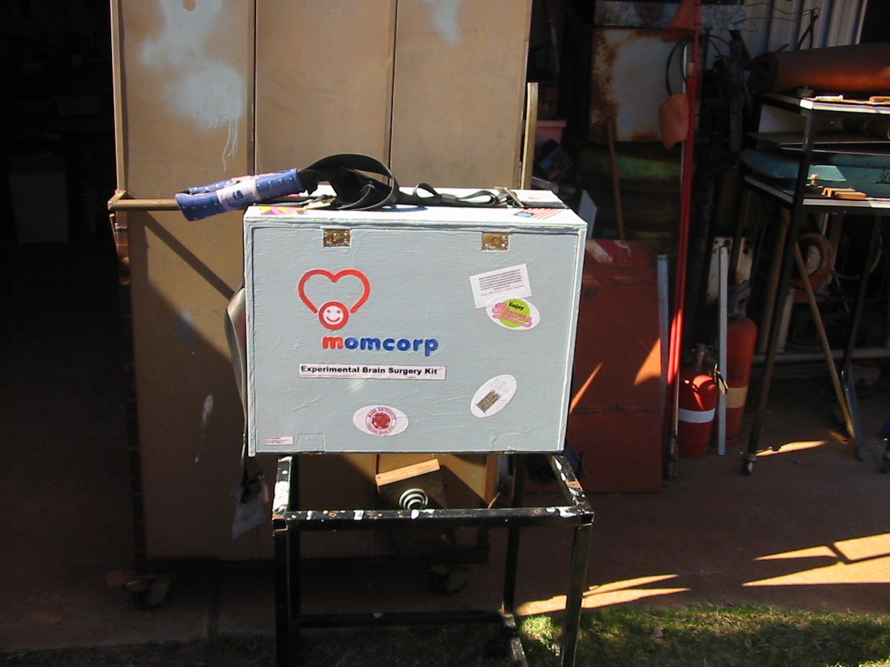
In keeping with the Futurama theme, and tying in the fact that this desk is designed and made for use in electronics and microprocessor experimentation, I decided to theme the trim on the concept of the desk being a "Momcorp" product, a prototyping/ repair kit for Momcorp products using microprocessors.
From that concept, it wasn't too hard to look at this as an "Experimental Brain Surgery Kit" (Always wanted a tool box with that written on it!!!) for robots and robotic devices.
I created a version of the Momcorp logo (The nicer one, not the authoritarian vertical MOM one) and decoupaged it to the front and back of the desk. I printed the logo I made on the thinnest paper I could find, then spray painted the back white to increase the opacity - I clear coated the front to stop the ink running.
I then got to thinking... if I was in the year 3xxx and a technician, I wouldn't leave my travelling toolbox looking so bland. It would have stickers on it ....
All of the "stickers" where clear coated over (to stop the inkjet ink running when varnished), and most were spray-painted white from the back to improve the contrast and opacity - but not all. A few of the images were deliberately scuffed and aged just to add a "worn look" to them. - given the less than perfect cabinetry, a few bumps and scratches here and there will be well and truly "in character: A couple of the stickers were not painted white from the back so they'd appear to be made from newsprint paper... just for variety.
Stickers include: The vitruvian robot drawing, robo-fresh, the feminista bumper sticker, WWZJD.....
several Slurm stickers, Mars University, Scary Door, a binary expression....
Nixon's reelection campaign poster, robot oil sticker, "I love Snu-Snu" bumper sticker (who doesn't?)....
A hypno-toad sticker, a trekkie bumper sticker, robot oil ad, more slurm.....
more Slurm (it really is addictive!!!), the Earthican flag, a "Morbo" bumper sticker, HAL institute sticker, a NNY sticker, and a "protest sticker".
The protest sticker was written up in the Futurama "alien" font - it's the font used throughout the show. I won't give out the meaning, but it's a very well known sentiment amongst those whom nanny-states will try and govern.
That's it for the trim - I did have a bachelor chow sticker, but it got damaged during painting (Wind got it while it was wet) - I was going to put a DOOP sticker on as well, but it was starting to look cluttered... we'll see.
All that's left now it to show the unit with the contents in it. That article is as much for the PICAXE forum as any other groups since they helped me with the shopping list of things going in there.
Painting was straightforward...
Undercoat,
filling,
masking and
top coats of "Bender grey" (the darker grey used to paint Bender's arms and legs)
In keeping with the Futurama theme, and tying in the fact that this desk is designed and made for use in electronics and microprocessor experimentation, I decided to theme the trim on the concept of the desk being a "Momcorp" product, a prototyping/ repair kit for Momcorp products using microprocessors.
From that concept, it wasn't too hard to look at this as an "Experimental Brain Surgery Kit" (Always wanted a tool box with that written on it!!!) for robots and robotic devices.
 |
| Figure 1 - Momcorp logo pages drying after clear-coating and spraypainting |
 |
| Figure 2 - Decoupaged logo on door of field desk |
I then got to thinking... if I was in the year 3xxx and a technician, I wouldn't leave my travelling toolbox looking so bland. It would have stickers on it ....
- from places I'd been authorised into (HAL institute for criminally insane robots),
- stickers from products (Mom's old fashioned robot oil, bachelor chow, slurm),
- stickers which reflected the world around me (political, social fads, social commentary, humourous),
- and at least somewhere I'd have my name.
 |
| Figure 3 - several pages of "stickers" drying after painting |
 |
| Figure 4 - Back of Field desk with stickers applied |
 |
| Figure 5 - Door of Field desk (Outer side) |
 |
| Figure 6 - LHS of Field Desk |
 |
| Figure 7 - RHS of Field desk |
 |
| Figure 8 - Top of Field desk, including "protest sticker" |
The protest sticker was written up in the Futurama "alien" font - it's the font used throughout the show. I won't give out the meaning, but it's a very well known sentiment amongst those whom nanny-states will try and govern.
That's it for the trim - I did have a bachelor chow sticker, but it got damaged during painting (Wind got it while it was wet) - I was going to put a DOOP sticker on as well, but it was starting to look cluttered... we'll see.
All that's left now it to show the unit with the contents in it. That article is as much for the PICAXE forum as any other groups since they helped me with the shopping list of things going in there.
Thursday, June 16, 2011
Field desk - part 4 - Tray and lighting (additional information)
A little more information on the lighting, and a quick article concerning the tray for the top shelf.
About 5 minutes after finishing part 3 of this series, I was filing the folder for that article when I found the additional photos I took as part of the lighting design...
Photos of the two lights I trialed, including the LED lamp I used in this project, and a photo of the desk with a piece of DIN rail used to measure length and placement of the lamp.
Paper Tray - Top Drawer
The other photos in this article cover the construction of a "paper tray" which is designed to fill the top shelf of the field desk. I plan on keeping an A4 notebook, CDR (with manuals), a couple of pens, etc in that shelf. The easiest way to achieve this is to have a drawer.
The paper tray is simply folded up from sheet metal (more of my salvaged colourbond "signwhite") to make a simple tray, with a folded top edge on three sides, and one extended edge on the front. This extended edge forms a handle which allows the drawer to be pulled out from the shelf.
Since I haven't had the time to build a finger brake yet (still on the ever growing "things to do" list), I did all folds using the clamp over bar, wood and hammer method. One thing I found during that exercise was that you shouldn't hammer anything whilst you have a cold - all it does is screw up your inner ear whilst your sinuses are stuffed - Not a nice sensation.
Once folded up, a couple of pop rivets to hold it all together and then it's painted up in "Bender Grey". In fact the entire exterior of the desk will be painted "Bender Grey" and will carry a suitable theme in the trimmings.
The painting and trim of the field desk itself will be the next article, then all that's left is a brief discussion about contents and that project is complete.
About 5 minutes after finishing part 3 of this series, I was filing the folder for that article when I found the additional photos I took as part of the lighting design...
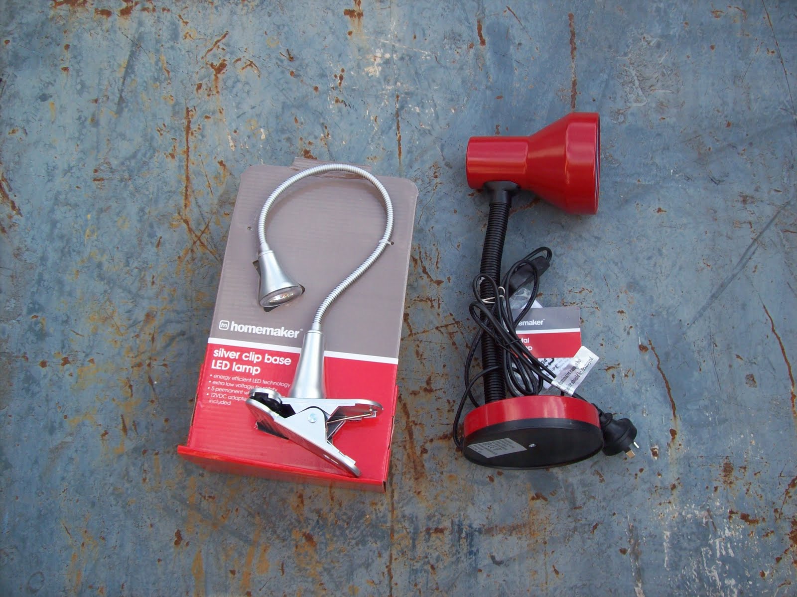 |
| Figure 1 - Lamps tested for use in the desk - LED lamp on left, incandescent on right |
 |
| Figure 2 - Trial of lamp placement using DIN rail |
Paper Tray - Top Drawer
The other photos in this article cover the construction of a "paper tray" which is designed to fill the top shelf of the field desk. I plan on keeping an A4 notebook, CDR (with manuals), a couple of pens, etc in that shelf. The easiest way to achieve this is to have a drawer.
 |
| Figure 3 - Sheet metal cut out, prior to folding |
 |
| Figure 4 - Drawer in place on shelf |
 |
| Figure 5 - drawer painted |
 |
| Figure 6 - Finished drawer showing folded handle on LHS |
Field desk - part 3 - Electrical System and lighting
Electrical services into, and within, the field desk.
Electrically speaking, the field desk will have one power lead into the desk, with a double switched GPO, and a variety of DC power sources available. A task light will also feature in the design.
Electrical enclosure
The electrical enclosure was designed to contain all components, and attach in the top of the RHS bay. The front panel will contain all interfaces - plugs, switches, etc. The original design was to use an old PSU from a 1900 series switch, but upon checking the PSU, it was found to have some of it's pins non-commissioned (-12V and - 5V) - thank fully the size of the enclosure was dictated by the GPO, and banana sockets, this meant I had room to look at alternate options.
The front panel holds all connections, and has the receptacle for the light in the top RHS. - The receptacle is simply a short piece of DIN rail, and the lamp holder sits inside the rail.
The front panel of the power box is made of 3-4mm thick plexiglass, drilled, cut filed to hold the GPO, IEC socket, and banana posts. To prevent scratches showing on this panel, I marked the terminal values on from the back, and then spray painted over them from the back - this means the paint cannot be scratched from outside the case. Interesting note was when the paint dried, I could suddenly see this invisible cracks around the banana posts - it looks almost surreal to see "reversed cracks" filled with paint.
The enclosure is designed to sit in the top of the field desk, therefore all ventilation is through the floor (or the front) - I simply replaced the floor with some punched mesh, and then used sheet metal shields to redirect any airflows from the back, through the PSU fan, through the PSU, and then into the front section, through the enclosure floor. Each "side" of the PSU has around 12 sq inches of floor vent available to induct, or expel air.
The enclosure (power box) is held in the top of the desk by means of some brackets, and a folded lip at the back. None of the retaining hardware obscures the ventilation grid, and removal of the power box is accomplished with the removal of one screw, since the forward brackets tilt to permit removal.
The only parts of the enclosure which are painted are those parts visible in normal use - ie the front panel/s, and the bottom. The sides were deliberately not painted since the paint would simply rub off on the walls of the cabinet during insertion, or removal.
Lighting
A 12V LED lamp was purchased from the local variety store (KMart) - I had looked at an incandescent lamp, but compared to the LED lamp, it was pale and yellow. I considered one of the halogen lamps I use when I sew, but they do throw some heat, and I considered that would not be wise in the planned location - not to mention wasted energy as heat.
The lamp was gently disassembled (no warranty voiding yet) and tested for it's ability to "hold up" from a horizontal plane - it was discovered that if held at a 45 degree angle, the lamp's "flexible arm" would support the lamp to the maximum reach. Based on that, a bracket was made (from plexiglass) to hold the base at 45 degrees. The bracket slides into a short length of DIN rail which is used as a track. This track is part of the enclosure and is accessible from the front panel.
The lamp will be removed to close the door, so the plug which supplies power to the lamp was cut through the opened switch, and additional wiring soldered on. The wiring is then terminated to the connections for 12VDC (and COMmon) so the lamp will run whenever the PSU is on. This should have worked but during final testing it was found that the light actually needed more than 12 VDC - the "wall-wart" power pack put out 14VDC unloaded - typical for a 12VDC cheap supply, so I connected it to 12VDC - the light was so dim, you'd have thought it was off. I moved the negative cable from the COM to the -5VDC (giving 17VDC) and she lit up beautifully. - Now the cables are between the -12VDC and the 3.3VDC connectors giving 15.3VDC for the light.
PSU
Since the planned 1900 PSU was abandoned, the next most affordable option was to use a surplus ATX PSU. There are a number of articles on the web which discuss the conversion - most centre on forcing, or redirecting the softpower "On/Off" wire, and providing a load to stabilise the regulation circuitry. I started going through my collection of surplus ATX PSUs looking for a reasonably low powered unit which worked, and could be used in this project. I tested some of my surplus ATX PSUs and found a 450W which worked OK. I originally planned on using a "wiring harness" to connect everything up, but the space was too tight for that option.
What I ended up doing was opening the PSU case, removing the IEC socket (and other mains supply switch and components) and soldering in a hardwired cable. At the same time I cut the ATX plug off, and trimmed all HDD/FDD cables at the first Molex connector. This gave me a bundle of wires about 350mm (14") long. I tied the green wire (PSU_ON) and one black wire (COM) to a toggle switch, and then grouped all other wires together based on their colours and connections within the PSU. Purple (Standby 5V) and the Grey (PSU_OK) cables were tied off inside the PSU since I didn't need them.
The rest were soldered to brass tabs made to suit the backs of the banana sockets (with 2 sets each for COM (Black) and 5V (Red)) The blue and white wires (-12V and -5V) looked so lonely on their tabs when all other tabs had 5 or more cables soldered in. A 7W wirewound 10 ohm resistor was added across the 5VDC rail for a regulating load (although most supplies theses days don't seem to need that - I'll remove the resistor for now and see if the PSU behaves)
As mentioned previously, the enclosure needed some way to direct air through the PSU fan, and back out of the enclosure. I accomplished this by bending up sheet metal dividers - the one closest to the front also being Earthed, and the one at the back being used to restrain the PSU, and block the holes in the casing where the IEC sockets were removed.
All Done!!! (although I haven't put in the 2 self tappers in the top corners yet!!)
As can be seen in the background of some photos, the desk cabinet is already being painted. The next article will cover the painting and trimming of the desk.
Electrically speaking, the field desk will have one power lead into the desk, with a double switched GPO, and a variety of DC power sources available. A task light will also feature in the design.
Electrical enclosure
The electrical enclosure was designed to contain all components, and attach in the top of the RHS bay. The front panel will contain all interfaces - plugs, switches, etc. The original design was to use an old PSU from a 1900 series switch, but upon checking the PSU, it was found to have some of it's pins non-commissioned (-12V and - 5V) - thank fully the size of the enclosure was dictated by the GPO, and banana sockets, this meant I had room to look at alternate options.
 |
| Figure 1 - Basic Enclosure unpainted |
The front panel of the power box is made of 3-4mm thick plexiglass, drilled, cut filed to hold the GPO, IEC socket, and banana posts. To prevent scratches showing on this panel, I marked the terminal values on from the back, and then spray painted over them from the back - this means the paint cannot be scratched from outside the case. Interesting note was when the paint dried, I could suddenly see this invisible cracks around the banana posts - it looks almost surreal to see "reversed cracks" filled with paint.
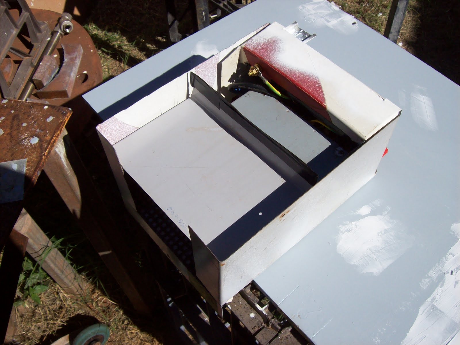
The enclosure is designed to sit in the top of the field desk, therefore all ventilation is through the floor (or the front) - I simply replaced the floor with some punched mesh, and then used sheet metal shields to redirect any airflows from the back, through the PSU fan, through the PSU, and then into the front section, through the enclosure floor. Each "side" of the PSU has around 12 sq inches of floor vent available to induct, or expel air.
The enclosure (power box) is held in the top of the desk by means of some brackets, and a folded lip at the back. None of the retaining hardware obscures the ventilation grid, and removal of the power box is accomplished with the removal of one screw, since the forward brackets tilt to permit removal.
 |
| Figure 2 - Close up of front panel, with first sheet metal divider removed |
 |
| Figure 3 - Mesh base to enclosure used for ventilation of PSU |
A 12V LED lamp was purchased from the local variety store (KMart) - I had looked at an incandescent lamp, but compared to the LED lamp, it was pale and yellow. I considered one of the halogen lamps I use when I sew, but they do throw some heat, and I considered that would not be wise in the planned location - not to mention wasted energy as heat.
The lamp was gently disassembled (no warranty voiding yet) and tested for it's ability to "hold up" from a horizontal plane - it was discovered that if held at a 45 degree angle, the lamp's "flexible arm" would support the lamp to the maximum reach. Based on that, a bracket was made (from plexiglass) to hold the base at 45 degrees. The bracket slides into a short length of DIN rail which is used as a track. This track is part of the enclosure and is accessible from the front panel.
 |
| Figure 4 - Power box in place in field desk with lamp inserted |
PSU
Since the planned 1900 PSU was abandoned, the next most affordable option was to use a surplus ATX PSU. There are a number of articles on the web which discuss the conversion - most centre on forcing, or redirecting the softpower "On/Off" wire, and providing a load to stabilise the regulation circuitry. I started going through my collection of surplus ATX PSUs looking for a reasonably low powered unit which worked, and could be used in this project. I tested some of my surplus ATX PSUs and found a 450W which worked OK. I originally planned on using a "wiring harness" to connect everything up, but the space was too tight for that option.
 |
| Figure 5 - Wiring harness (Mk 1) which was too big for use |
 |
| Figure 6 - Internals of ATX PSU being modified for use. |
 |
| Figure 7 - Modified PSU in enclosure with earthed divider panel. |
 |
| Figure 8 - Completed power box with second divider in place for ventilation redirection. |
 |
| Figure 9 - Completed power box ready for use. |
Subscribe to:
Posts (Atom)
