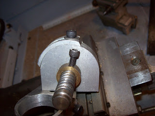
Figure 1 - plate carrier/ worm assembly
Another piece of metal is made which has a 1" diameter spigot which is about 0.5mm thick. This spigot is made to match the hole in the middle of a hard-disk platter. A piece of 1/4" brass has been drilled in to intersect the edge of the hole and a corresponding notch is cut into the platter to stop it rotating. A cover plate is made with a corresponding hole and screw to lock the plate (Hard-disk platter) in place. Yes that's chatter marks from turning... that work was done on a stub arbor.

Figure 2 - plate carrier with spigot

Figure 3 - Plate mounted on spigot
The plate retainer is basically a brass plate with a hollow spigot on it. The worm shaft passes through the spigot, whereas the sector arms rotate about the spigot.

Figure 4 - plate retainer holding plate on spigot
The other main feature of the plate carrier is that the part which carries the plate can be rotated through approx 90 degrees. This was cut from a piece of plate, mounted on a stub arbor, and turned to match the curvature of the mating piece. A slot was cut in the side rim whic mates to a threaded hole in the main part. The purpose of this is to allow the plate carrier (and attached plate) to be rotated independently from the worm itself over a 90 degree range. Why? Imagine you mount something requiring 13 divisions in the chuck on the dividing head, and then need to index another section of the same piece with 19 divisions and one section needs to be perfectly in line. I can mount up, cut one set of indexed points, apply the spindle brake, then change the plate, and move the plate to align exactly with one plate hole, then re-commence indexing for 19 positions. Maybe something which will only happen once in a blue moon, but it cost me little but time to add it into the design.

Figure 5 - one extreme of plate carrier adjustment

Figure 6 - another extreme of plate carrier adjustment
The worm itself was cut down from the original shape when removed from the sewing machine. A triangular groove was turned in it which intersects with a pointed socket-head screw used to lock it in longitudinal position, and a pair of flats and 1/4-20 thread was cut into the end. These correspond with the sector arm, and retaining nut respectively.

Figure 7 - worm in carrier showing flats and threaded sections
All bushings in this part of the dividing head are simple yellow brass, not bronze. At the time I built this I could get surplus electrical test probes from the local salvage place for a couple of dollars. Each probe comprised about 12" of 1" diameter nylon with a 1/4" bore, and a corresponding length of 1/4" brass rod in the middle. A few other bits made up the probe, so I was able to get nylon (for rail buttons) and brass rod quite cheap. The interface disk from the probe was used to make the plate retainer since it was 1 1/2" in diameter, and about 1/4" thick. I miss that shop. Pretty much all the remaining brass I have is from various scrap merchants, or salvaged from all sorts of junk.
I'll cover generating plates and direct indexing next.

No comments:
Post a Comment