Showing posts with label tools. Show all posts

Saturday, January 15, 2011

shed tips - foaming tools, and disposable nozzles

Foaming tools

Basically a number of tools come in either blow-mold cases, or metal cases with blow-mold inserts. The decision to use blow-mold is based on providing a close fit to the tools in the case, without the cost of the old style wooden inserts.
There is a problem with the blow-mold inserts - breaking down due to age and vibration. the plastic liner breaks down and cracks apart due to the weight of the tools and eventually becomes useless.  Following the advice of those wiser people, I take the time to fill the backs of blow-mold liners so there isn't as much "give" in the liner, and the tools don't break it down as much (if at all)

The basic principle is to fill the voids in the back with something disposable and durable - currently I use expanding foam (the single expansion type, not the one which expands again when contacted by heat or water), but in the past I've used silastic (caulking sealer) bulked up with either sawdust, or scraps of foam, wood, or even general shed rubbish (broken hacksaw blades, etc)

Using foam
Access the underside of the blow-mold liner


fill the gaps with expanding foam


apply a sheet of heavy card (old filing cabinet suspension files) and weight it down until the foam cures


if you remove the card,you will find the foam pretty much filling all large gaps, but maybe missing some of the smaller ones - sometimes I refill them, other times simply leave them.


The photo below shows one weighted down liner, the other simply left uncovered and unweighted during the foam cure


As seen below, the unweighted one cured with large air bubbles under the foam, basically providing no support to the liner and the tools. The cut way pieces of cured foam aren't tossed away, instead they are pressed into the gaps, then refoamed and covered and weighted. As mentioned at the top of the article, the filling doesn't need to be anything flash, so offcuts of foam work fine.


I know people who use plaster for this some task - works well - my only concerns are the weight, and the holding of moisture inside the tool case.


Disposable nozzles for foam dispensing
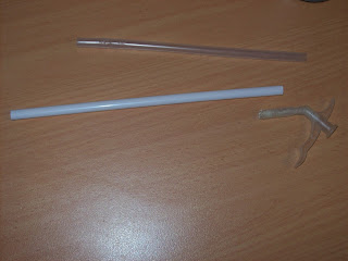
The foam dispensing can nozzle - the sales guy from ramset told me that the expnding foam valve is a single function unit as mandated by the nannygovt  - as a result I buy my can (local trade store) and collect up a handful of straws from macdonalds. I cut the supplied nozzle tube at 1" (25mm)


and slide the macdonalds straw over the original (shortened) nozzle tube - this makes cleanup much easier (throw the straw away, and blow out the short piece) - As long as I schedule all my foaming for one day, I can usually use up the whole can before the internally sabotaged valve locks me out of the can.


Upcoming posts -
New life for an old welding helmet, and the lathe stand/cabinet

Sunday, May 2, 2010

"free" pegboard - shed tip #1, and magnets

A useful shed tip which saved me some money when I first set up my shed here. I know many people who adore the look of pegboards, with all their tools neatly silhouetted on the board, easy to see what you have, and if anything is missing.
Personally I'm not too fussed on having my tools on display (seems hypocritical after posting about tooling - bear with me), but I do like having commonly used tools in a location that is easy to get to quickly.
When I set up my shed, I considered pegboard, but it's not cheap. I then came across the idea of using an old hollow core door.
These doors get tossed out all the time around here as homes are refurbished. I grabbed some for use as trestle tops, and I took one of these and screwed it to the shed wall, effectively cladding that section of the wall with the door. The door is screwed on horizontally, and flush with the wall top.

Peg board works by having a 6mm (1/4") masonite board, pre-drilled with holes, mounted with a 1" (25mm) gap behind it for hooks to pass through.
A hollow core door is a sheet of 5-6mm masonite, with a 1" gap filled with a light honeycomb of cardboard, and then finished with another 5-6mm sheet of masonite. The whole assembly is edged with a solid wood frame which is around 35-50 (1 1/2 - 2") wide... other than the pre-drilled holes, the hollowcore door would pass for pegboard on a frame.


The photo above shows the door, with holes drilled anywhere I want them, things screwed to the door, things hanging off it... lots of options.
Once the door is mounted on the wall, I simply started screwing things to it, corner brackets for heavy duty hooks, blocks of wood for holding squares or saws. I can drill holes where ever I want for hooks, the tail of the hook simply crushes the internal cardboard if it's in the way.

Another thing which is good about the doors is that I could screw hard drive magnets to it where ever I want. I dismantled a number of harddrives over the years - mostly for collecting material for the furnace, but I also salvage useful components such as platters, magnets, and bearings.

The magnets get used for all sorts of things, but one common use is for holding things up. The photo below shows magnets screwed to the door and labelled for the hammers they hold.


I've yet to find a hook I'd trust for holding up my sledge hammers, but is easy to remove, or replace the hammers on. The photo below shows my club hammer attached to the wall via the magnet.


I'd show a better picture of some of the other things hanging on the wall, but it's hard to get a decent photograph through all the mess in the shed.

The magnets also get used for holding charts to the roof of the shed. I ran out of wall space in my shed pretty quick. Between shelving, door, tool storage, and a bench, the walls seemed to disappear pretty quick, so I stored my thread/ drilling charts on the roof. I simply covered the charts in contact, and then used some magnets to attach the corners to the roof.


So shed tip #1 - free pegboard by using hollowcore doors, and drilling your own holes where you want them, (as you need them, etc)

Bonus tip - save hard drive magnets for use for holding tools to walls, etc. I use one magnet for a 35lb sledge hammer - they are dynamite for holding, clamping, etc - and free for minimal labour.

Saturday, April 10, 2010

Bender's antenna - part 2

Before I get too far into the ball and how the antenna holds together, I found this slightly blurry photo of the washer pressed into the bottom of a deodorant lid to stop the lid collapsing in the lathe chuck. The washer was nothing special, not even properly round, just an old thrust washer from the junk box.
So, I've mentioned the three components which make up Bender's antenna.. the ball at the top, the tapered shaft in the middle, and the dome at the bottom.
The ball in this model was an old deodorant ball (Lynx if it matters, but they all seem to be the same size). I considered gluing it to the model, but didn't trust the join. I decided the best approach would be to affix the ball to a shaft which ran through the tapered shaft, and was retained in the dome, or valve. I drilled a 1/4" hole in each of the balls, and then prepared some 1/4" shaft. The shaft was threaded at the end which would be away from the ball, and the "ball end" was hacksawed for a length of around 20mm (3/4") along the middle. I then made 2 small wedges of scrap steel which had a narrow point, but then a steep taper followed by parallel sides of 1/4". The point was to allow a friction fit in the hacksawed slot, the steep taper to force a wide split in the slot once driven in, and the parallel section just for length.
The idea was to use the wedge to lock the ball onto the shaft by making it wider than the 1/4" hole. I mixed up some 30min epoxy resin, and filled the inside of the ball with a 50-50 mix (by volume) of resin, and brass swarf (from under the lathe).
I put the wedges in place (held with a single turn of sticky tape) and carefully inserted the shaft into the ball via the hole, then tapped the shaft down against the wedge so the shaft would expand inside the resin filled ball. The photo below shows the two balls with their shafts waiting for the resin to cure.

The photo above also shows the dome and shaft assembled. This was done by half filling the dome with some expanding foam, then forcing the turned valve and shaft into it and letting the expanding foam lock in under the lip I turned. Once the foam was set, a simple trim with the knife cleaned away any spillage, or leakage.
I tried using a smear of the foam to fill the small gap in the ball seam, but it didn't really take too well.

The threads cut on the end of the shaft (with a die - I'm still working on building a driven leadscrew for my Taig) were matched with a brass sleeve nut I made up on the Taig. The brass was bored, then tapped for the thread, and then finish turned for the stepped bore in the valve. Once the lengths were finalised, I bored out some of the threads for easier assembly, and cut a tool slot in the sleeve nut. A similar tool slot was cut in the underside of the valve threads to make assembly easier. With the ball on one end of the shaft, and the nut at the other, the tapered shaft, and dome were locked together on the cut down valve, and the whole assembly was then placed on a spare extinguisher top for the last photo.

This extinguisher top is how the NuSwift DCP looked before I started cutting them apart - a large bronze boss in the top for the valve assembly, a smaller boss in the middle of the curve for the pressure gauge, a carry handle on the back.
A total of five extinguisher tops are used to make bender, one for the head, two for the feet cups, and two more which are cut up for patches on the others where the gauge bosses are cut out.

Why do I seem to have so many old fire extinguishers? I grabbed them when I was building and using my furnace/foundry. I was using the bottom halves to make cheap low use crucibles for my aluminium, brass and bronze furnace. I never threw the tops away since they had those big bronze valves, and bosses - the intent was to melt them down for stock. When I got the NuSwift DCP extinguishers, there were other extinguishers in the pile I could have had, but there was considerably more NuSwifts than any other type. Once I started bender, I would regularly collect other extinguishers to cut up for the arm and leg segments, but that didn't work out as well.

I will do up a page (or several) about the furnace and it's tools (including the "robot"), but that will be after I complete the documentation of Bender.

Friday, April 9, 2010

Bender's foundations - feet, legs, base - part 2

Once the pipe for the legs was cut and curved, I welded the cuts and welded the legs to the foot cups on the base. I didn't think to photograph it, but the next step was marking the top of the legs to be level with the base, and at the appropriate height. To do this marking, I used the trick used by cabinet makers, (and dressmakers) of using a block of "stuff" with a pointer and marker contacting the legs, and then rotated everything around to completely mark the legs. In this case the block of "stuff" was the body previously made, packed to height with some pieces of timber.

Once the legs were trimmed to the correct height and level, I tested the fit with a plywood disk I used to test the body of roundness.

A photo of the "high tech" tool stand I used to keep the tools off the welding table whilst I was working. The three grinders proved quite useful since the 9" (230mm) grinder was used with the 2.2mm wheel, the 4.5" (115mm) with a standard grinding wheel, and the 5" (125mm) with the 1mm cutting disks. Yes, I used the faceshield and earmuffs... I value my eyesight and hearing, and see too many of my friends from industrial backgrounds with hearing loss from exposure to these kind of jobs.

The leg joint plate was made by placing an appropriate strip of sheet on top of the crotch plate and drilling all four clearance holes at once. I then marked through the curved (elliptical) ends of the legs, and split the strip with two tabs - one on each leg, both pointing towards the middle of the crotch plate. I then welded captive nuts, and bolts in the joint plates so each leg has one bolt, and one nut for securing it.

The welds were ground back and touched up prior to painting, but the above photo shows the captive bolt on the left, with a nut spun on, and another bolt spun into the captive nut on the right.
I choose a single bolt for each leg to make alignment during assembly easier, but I wanted the extra strength of two bolts, hence the second bolt added into the captive nut.

As always, I like to stack the pieces together to see how my progress is going. This what Bender looked like at the end of the day making the legs. It's obvious I had been picking at all parts of Bender instead of completing one part, and then another.
Until the next installment...